An important feature of the circuits like the one designed (which is effectively a digital to analog converter) is maintaining the monotonicity.
It means, that for every change of set value to a value higher by one least significant digit, the output value also increases. Since I already had the simulation script, I simulated the voltage difference between consecutive steps:
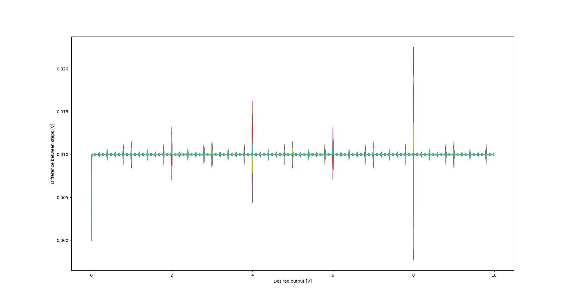
Every time the value drops below 0, the monotonicity is lost. It can be seen, that for some extreme combinations of component values within their specified tolerances, the monotonicity will be lost for transition from 7.99V to 8.00V. The ideal value (for ideal components) of change is 0.01V.
For my prototypes, the following values were measured:
| Set value | Measured value Prototype #1 | Measured value Prototype #2 |
| 7.99 V | 7.9854 V | 7.9791 V |
| 8.00 V | 8.0010 V | 7.9898 V |
The monotonicity is therefore maintained even for this nevralgic step for both prototypes.
Out of curiosity, I also checked how this plot would look like if I specified 1% resistors in the circuit:
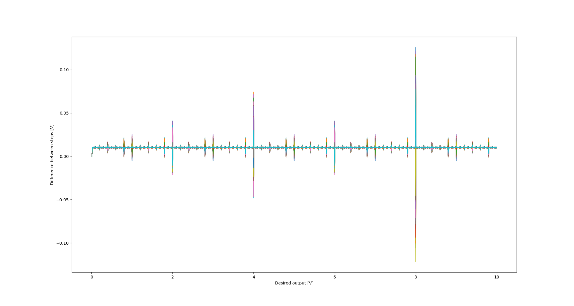
It can be seen that the possible loss of monotonicity is much more probable and more steps with possible loss can be observed.
Discussions
Become a Hackaday.io Member
Create an account to leave a comment. Already have an account? Log In.