 MaBe42
In the central part, the virtual ground is generated and also a kind of a triangular signal (very quick and dirty) which is needed for the conversion of the analog signal to PWM for the LEDs. Finally, the signals A, B and C from the legs are either directly used to drive the LEDs or differences are generated to have six different rhythms.
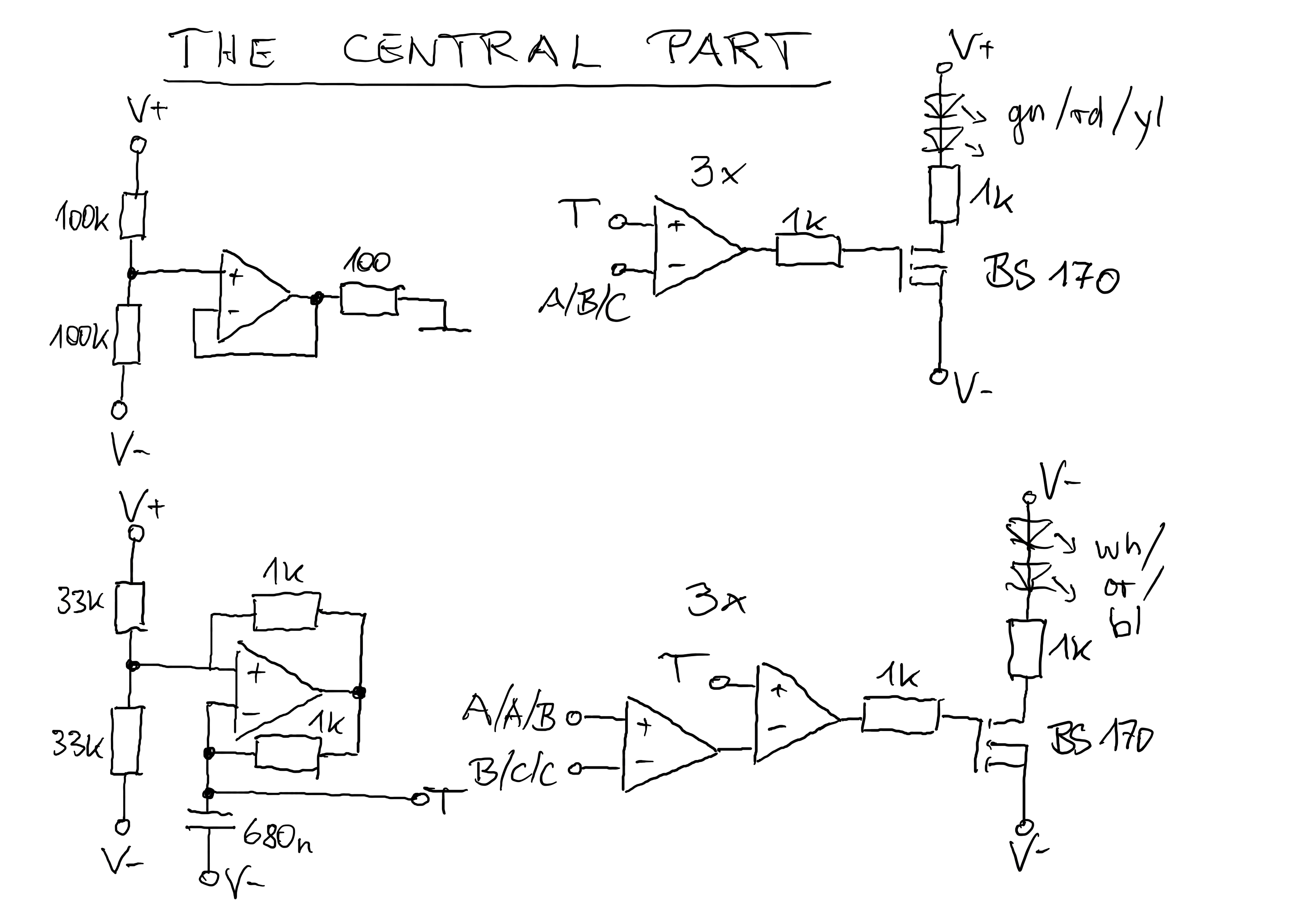
For the orange LED I took a 680R resistor instead the 1k to have it a bit brighter.
The FETs are not really necessary since the LEDs consume only about 5mA. But when I designed everything I was not yet sure how many LEDs I would need to drive.
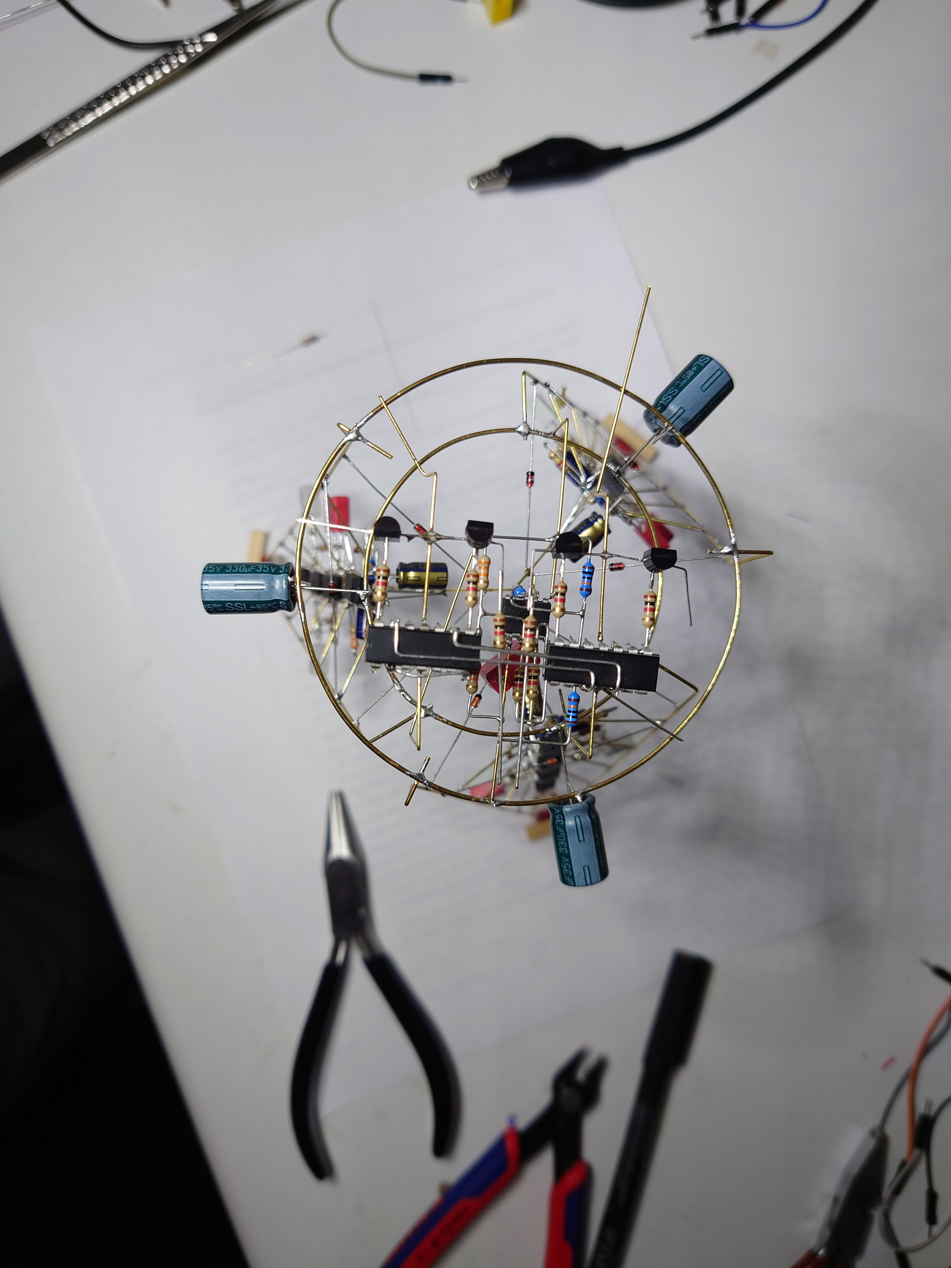
The large caps look cool and are needed to reduce some 50Hz ripple I had observed on some of the signals.
Discussions
Become a Hackaday.io Member
Create an account to leave a comment. Already have an account? Log In.