 Guillermo Perez Guillen
The STM32F429I board was programmed with GNAT Programming Studio 19.1 Developed by AdaCore. This part develops the most important control function of the system and I will detail below. The schematic diagram and the flowchart you can get at the end of this tutorial. As a reference for this project, I've used the following Ada tools:
- 1) examples such as demo_adc_polling, and demo_gpio_direct_leds;
- 2) Ada drivers libraries like STM32.User_Button, STM32.ADC, STM32.GPIO, and LCD_Std_Out; and
- 3) Theory sucha as arrays, and for and while loops.
The analysis of the code of the digital blood pressure monitor I've divided it into three sections:
- Inflation of the cuff,
- Deflation of the cuff, and
- Calculation of the Korotkoff sounds.
Our schematic diagram is shown below:
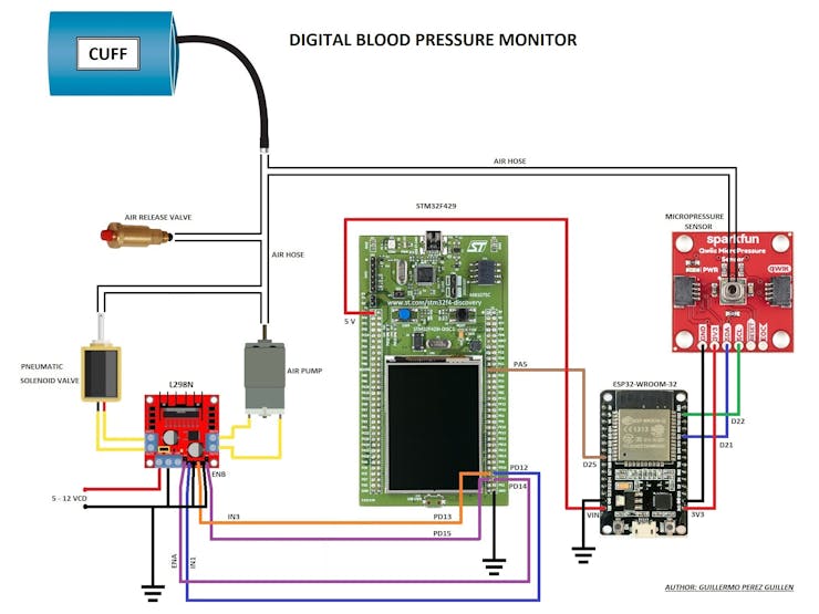
Schematic diagram
Discussions
Become a Hackaday.io Member
Create an account to leave a comment. Already have an account? Log In.