 Guillermo Perez Guillen
The hardware is assembled in a box for the best handling of the device, in the figure below we can see the box made with a 3D printer, and whose STL file you can get in the download section.
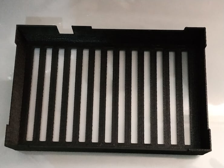
Box
Next, we join the solenoid valve with the connector through which the cuff can be connected.
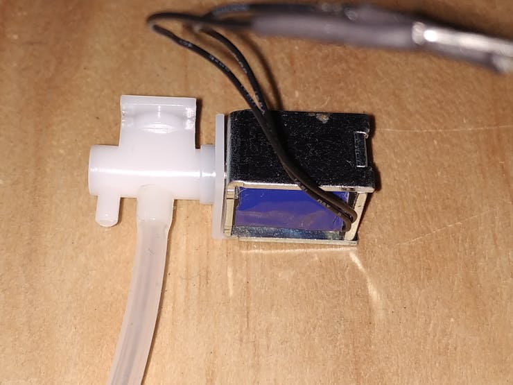
Pneumatic solenoid valve + connector
Now we glue these pieces with silicone over the box's groove shown in the figure below.
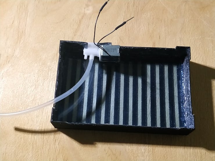
Glue the pieces indicated on the box
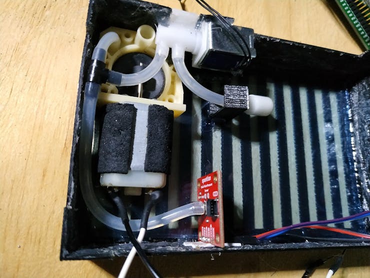
I have used a smaller air pump to best fit in the box. So, we join this air pump to the cuff connector with an air hose as shown in the figure below. Also we join the air release valve to the cuff connector with an air hose.

Air pump + air release valve
We connect the micro pressure sensor with the air pump with an air hose. Then we fix the pressure microsensor as shown in the figure below.
The next step is to fix the ESP32-WROOM-32 board as shown in the figure below.
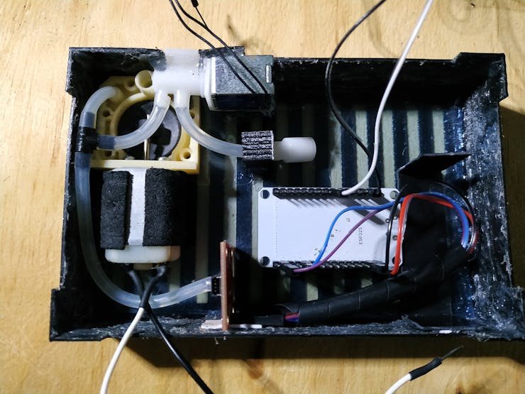
Fixing ESP32-WROOM-32 board
Finally, place the STM32F429I board and the L298N driver as shown in the figure below. All electrical connections are followed as in the schematic diagram.
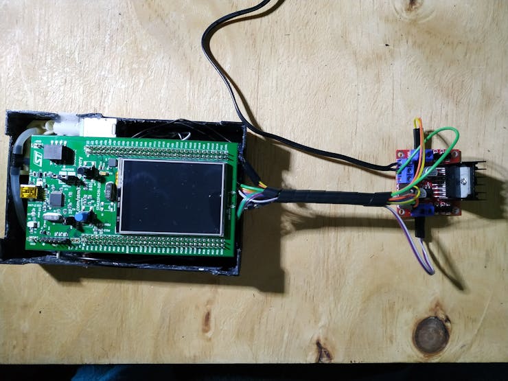
STM32F429I board + L298N driver
Discussions
Become a Hackaday.io Member
Create an account to leave a comment. Already have an account? Log In.