This is my first log entry. At this point I’ve spent a couple evenings testing the feasibility of the idea with a 1D version of the circuit on a breadboard. It doesn’t perform too well yet, but it does render a ball on my tiny CRT, and the ball can bounce off the floor and ceiling. Over the next few days I plan to optimize and clean up the circuit, so I can draw the schematics and share them here.
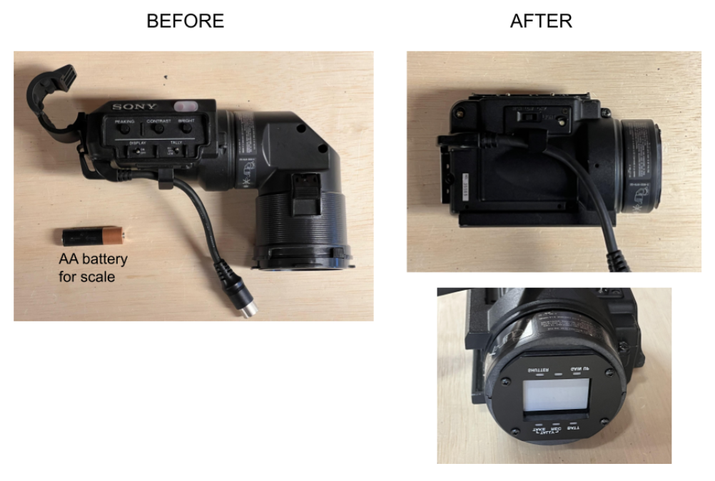
For this update I’ll focus on the part that is more “done” already, which is the display. The display is a modified Sony DXF-801 viewfinder. You can find them for $20 on eBay. To fit our purposes, I cut most of eyepiece off with a hacksaw. I also cut off the clamp in the back.
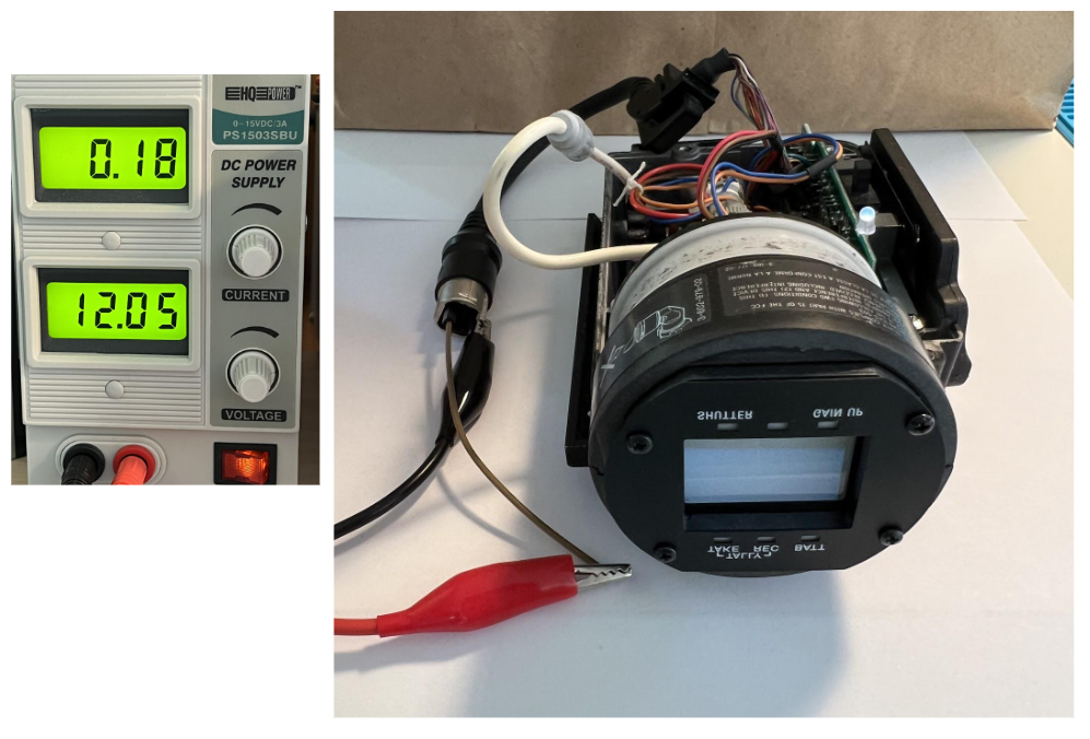
Using a service manual I found online, I looked up the power pins on the 20-pin connector (it needs 12V, 2.1W). From the schematic it appears fine to leave all other pins disconnected. Indeed, it powered up fine, and showed static on the screen. Yay!
To connect the CRT to our simulator circuit, we need to drive the horizontal and vertical deflection coils. The picture below shows the coils disconnected from the main board, highlighted in green. We’ll leave the other CRT connections alone (highlighted orange and red), those are for biasing the tube with high voltage:
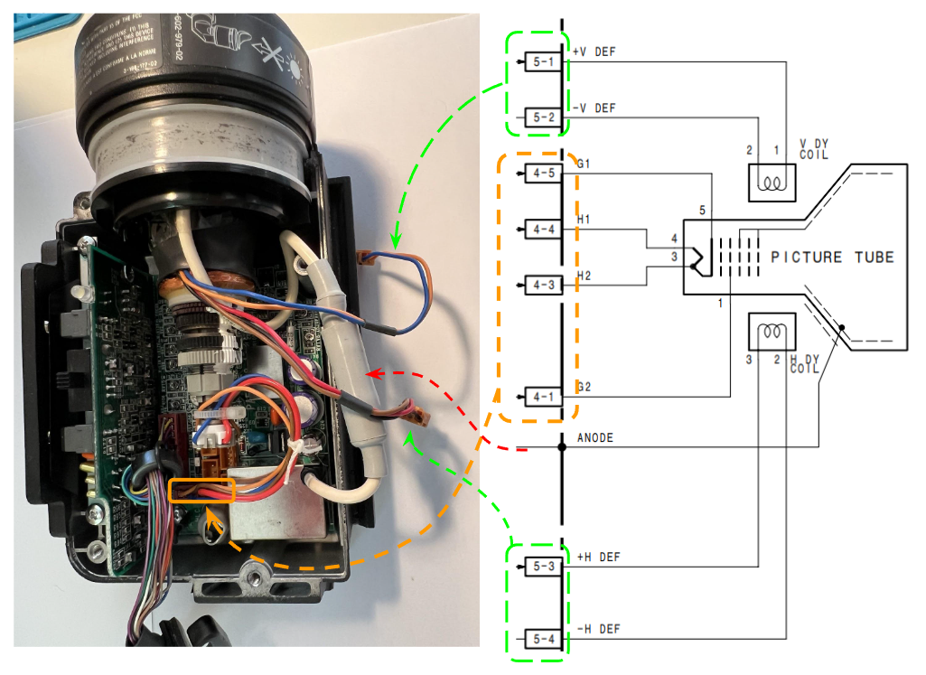
The orange connector also carries the heater and grid 1 (H1 and G1) voltages, which determine the brightness of the dot on the screen. I will leave that part of the circuit unmodified for now, and just use the external “bright” control knob, since it lets me turn down the brightness to basically darkness. Brightness control is important, because in normal viewfinder operation, the energy in the electron beam lights up the entire picture. If we instead make the CRT draw just one dot, the brightness of a full image is now concentrated to one point. We need to set the brightness very low, or we could damage the CRT.
Let's look at the deflection coils next. Our analog computer produces X and Y voltages that normally connect to an oscilloscope in x-y mode. For example, 0 Volts for X means horizontal center of the screen, more positive is more right, more negative is more left, etc.
With magnetic deflection coils, the beam angle is proportional to the current, not voltage. And since deflection coils are inductors, the current through them is i(t) = 1/L * \int v(t) dt. So we can’t just apply our X and Y voltages to the coil and expect the current to be proportional, like in a resistor. Instead, we need to produce a drive voltage that causes the coil current to follow the path we want. This is the perfect job for an op amp in the configuration below:
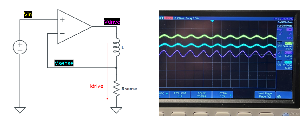
The scope traces here show the desired deflection waveform Vin (yellow), the resulting drive current waveform Vsense (cyan), and the drive voltage Vdrive (magenta) produced by the op amp. The yellow and cyan waveforms are identical because the negative feedback loop ensures that Vsense = Vin, and therefore, Idrive is proportional to Vin.
NOTE: the circuit above is simplified to illustrate the feedback mechanism. The real circuit doesn’t drive the coil directly from the op amp; there is a push-pull transistor stage in between. A fair amount of current is needed to deflect the beam all the way to the edges: about 50mA vertically and about 200mA horizontally. I’ll post the full schematics once I have finalized them.
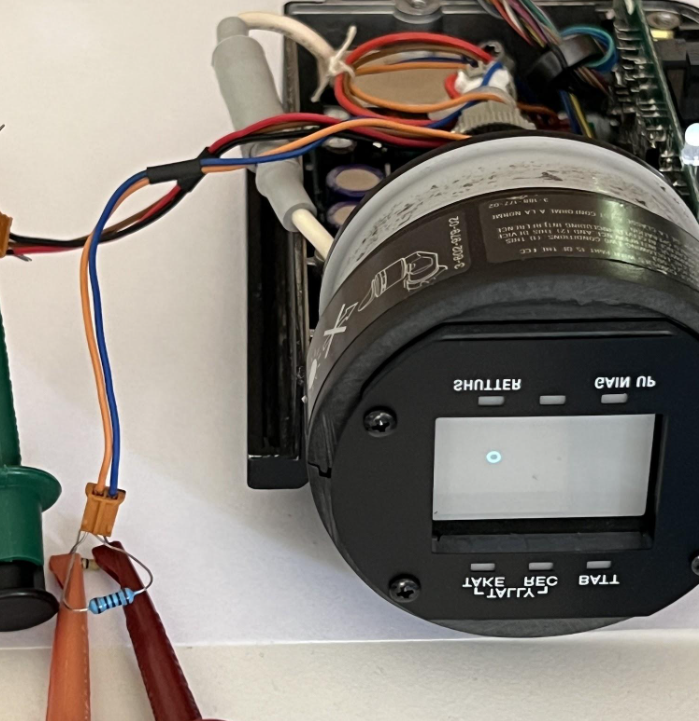
Finally, we have a ball on the screen! To waveform used to draw the ball in the picture below is a 1.3 kHz sine wave, with 90 degrees phase shift between X and Y.
Ok that’s it for today's update. Here’s what I’m planning to do next.
- During testing I destroyed a 2N3904 transistor driving the CRT deflection coils. I ordered beefier transistors, they came today.
- The ball on the display is not perfectly round near the corners of the screen. It’s not the most important thing to fix right now, but it bugs me, so I will try.
- Finish the rest of the circuit, e.g. add missing bounce logic in 2nd dimension.
- Dial in the simulation parameters, like mass, gravity, spring constants for the wall bounces.
- Draw up schematics
- Rebuild the circuit with better / tighter / cleaner layout
- Document operation and record video
 wlf647
Discussions
Become a Hackaday.io Member
Create an account to leave a comment. Already have an account? Log In.