 Ahron Wayne
I don't really remember what the state of the machine was the last time, but I know it's been a long time. Here's the state of the machine:

Still on the same wooden pallet it was shipped on? Why not?
Source: There is an analog PXS-925 in there again. It's convenient that I can use the existing instrumentation and the analog is much more reliable. I think it was a thousand bucks on ebay, good deal.
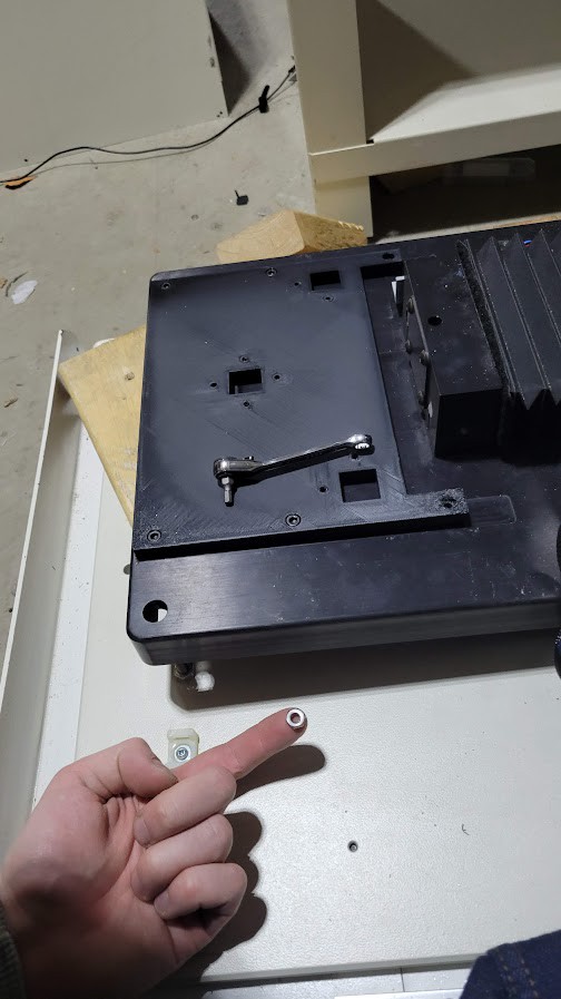
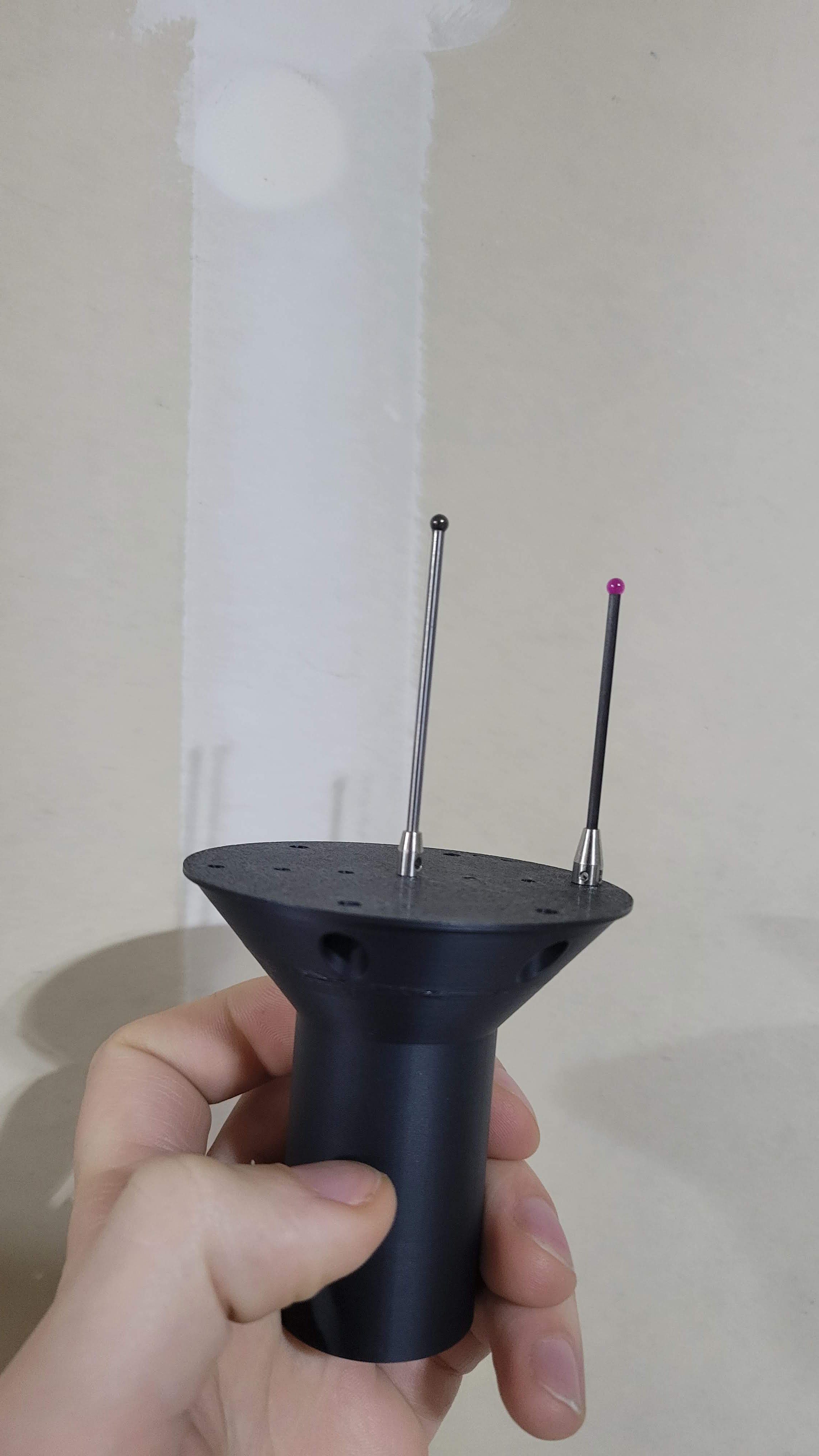
Detector: Did a bunch of work on this lately. New detector stand, much sturdier, from the general advice of my (day job) coworker, to "box it up", which is just solid advice on the account of making stuff sturdy. And shifted over 15mm to the left, 10 mm up (as far as I want to go towards the ceiling!).


The detector is mounted vertically. As in, the skinny end of the active area up. Here is a simple layout of the system:
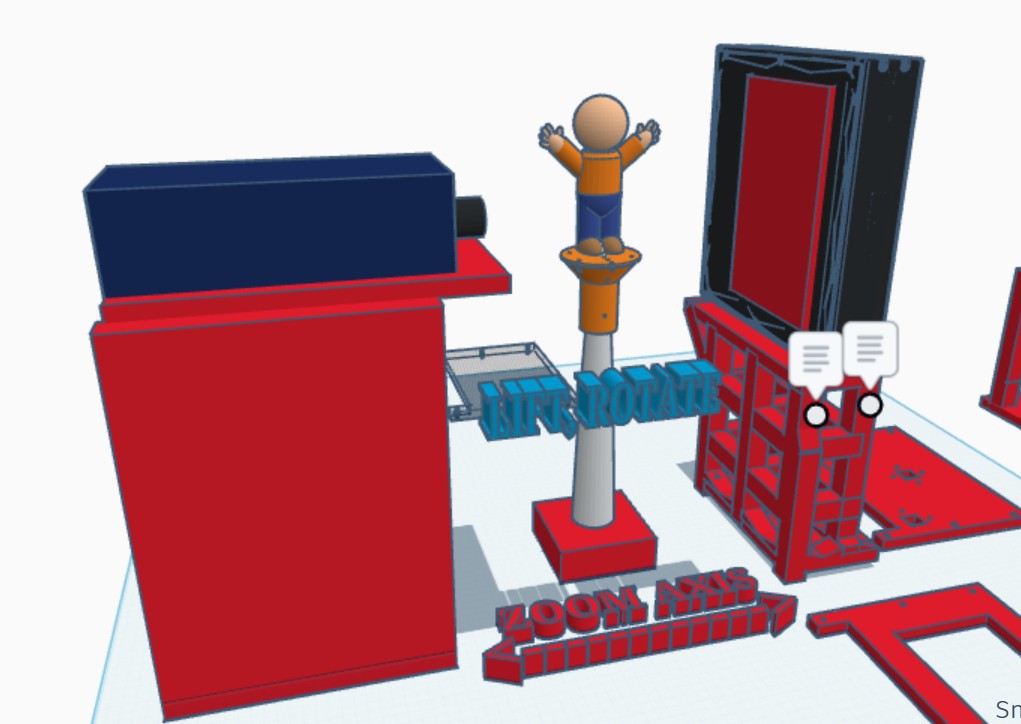
I'm expecting a lot out of this detector, being the most modern thing in the machine by 2 decades at least. It's a solid industrial flat panel, not superior to the original detector in every way from a pure physics standpoint - for instance, that one probably had a pretty thin scintillator, being geared more towards soft x-rays. But it is so much more stable and less noisy and that means faster images and also it's controlled directly by me instead of relying on a wacked out shutter mechanism which is huge.
Not being stuck with manufacturer's software is the challenge and reward of having a hack project like this. When you say something like, "what if you can do a scan along the lift axis instead of a tomography" and you just... can. Once you decode the serial command protocol. Look at that parallax!
And if I had a centering axis carried by the RA (easy!) could do all sorts of cool planar scans at high magnification. But now we have 2 things, the other being the rotating.
A gif like this is hard to make high resolution and high bit depth, especially for hackaday's (happy new year 2026!) 5 mb limit, but here are a few stills where you can see how a tiny bit of contrast can add up if it's aligned with the beam path:

(no prize for what object this is, but I'll be impressed if you know which pokemon).
and now boring stuff if you're not a huge nerd which I guess nevermind: currently I'm in the middle of trying to align the system. There's a few big parameters to clear, and then some low hanging fruit , and then it quickly gets out of my experience:
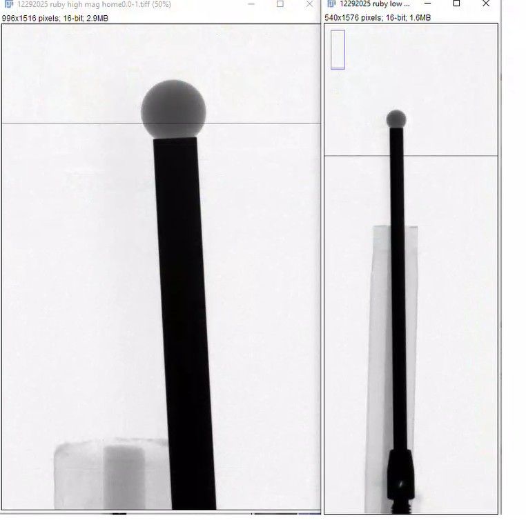
Source to Detector distance. And source to object distance. Like most calibration things in x-ray land, it involves balls.
Place a ball at magnification A, for example, with rotation axis as close as possible to the detector. Measure the projection on the detector. For instance, this ball is nominally 3.00 mm, and it covers 62 pixels, which are each 75 (74.98) microns, so the ball is apparently 4.64 mm and the magnification is like 1.5. Then you home to the other side, which is 164 mm closer to the source, and measure the ball as magnification... 5.5. I hate math, but if you see how much the magnification changed you get the source to the detector as like 350 mm, and the positions you scanned at like 64 and 228 mm, and I'm just rounding real data but you get the point...
Step Two (step 0?). Before this actually you should have aligned the RA to the source in the magnification direction. You can do this with a ball. You put the ball at the rotation axis, and move the magnification axis, and see if the ball moves side to side. if it moves side to side, you adjust the source or the rotation axis with a motor or micrometer so that the ball stays still.
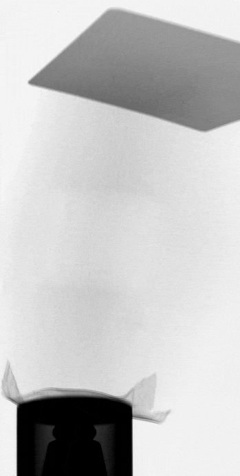
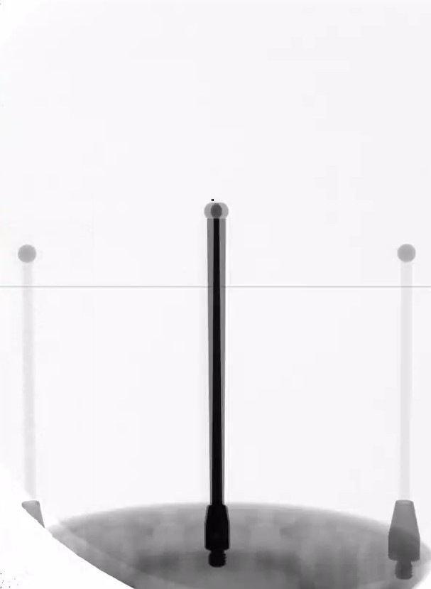
Step Three (step two?) Now that the source and RA are aligned along the mag axis, We want to see how centered our detector is along that. You can do so using balls.
Place a ball in the path of the beam, and move the magnification axis. The vertical location of the detector extent, where the centroid of the ball does not move up or down on the detector, is the central ray. In the above image, as we move along the zoom axis, the ball center doesn't stay put - the ball is not in the central ray. Ideally the central ray is at the center of the detector, but as long as we have enough cone from our source to cover our whole detector (we actually don't) it can be corrected in FDK reconstruction. In my case I'm off by 11mm but any higher and it will hit the ceiling.
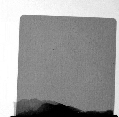
Next, similarly, you can determine how far you are off side to side, using a ball, rotate it 360 degrees and find the center on the screen, the difference from the center of the detector is the center shift. Very important for reconstructions. I'm like 3 pixels off now.
Finally, for some flavor, the in-plane roll of the detector is the easiest to check and the most important of pitch, roll, and yaw of the detector. it is much lower now (<0.1 degrees) from with the previous stand at closer to half a degree, ~10 pixels order across the screen.
So yeah I can do scans, and have freedom to do totally weird motor + acquisition geometries. Reconstructing is another challenge, but I have more confidence now that what I'm feeding the algorithms is at least right.
Thanks to balls.
Discussions
Become a Hackaday.io Member
Create an account to leave a comment. Already have an account? Log In.