Got the components and the boards, fhew, it took so much time!
Last time I tried to solder tiny SMD components it was so messy, I thought I will try easier method of solder paste.
Step one find a victim
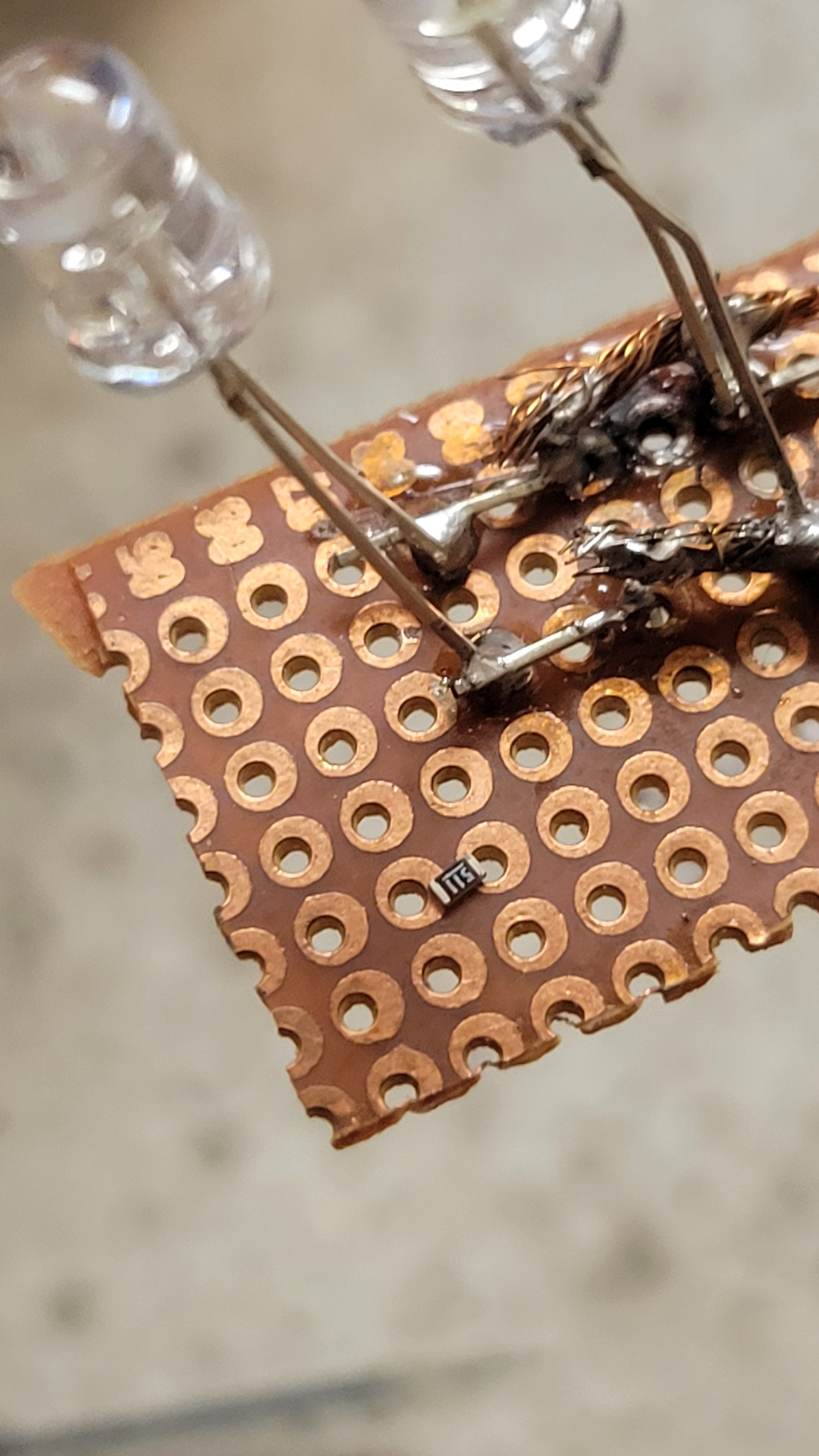
Let's say this tiny cute 500 ohm resistor of 0603 size code and some PCB board I don't need anymore.
Put some solder paste...
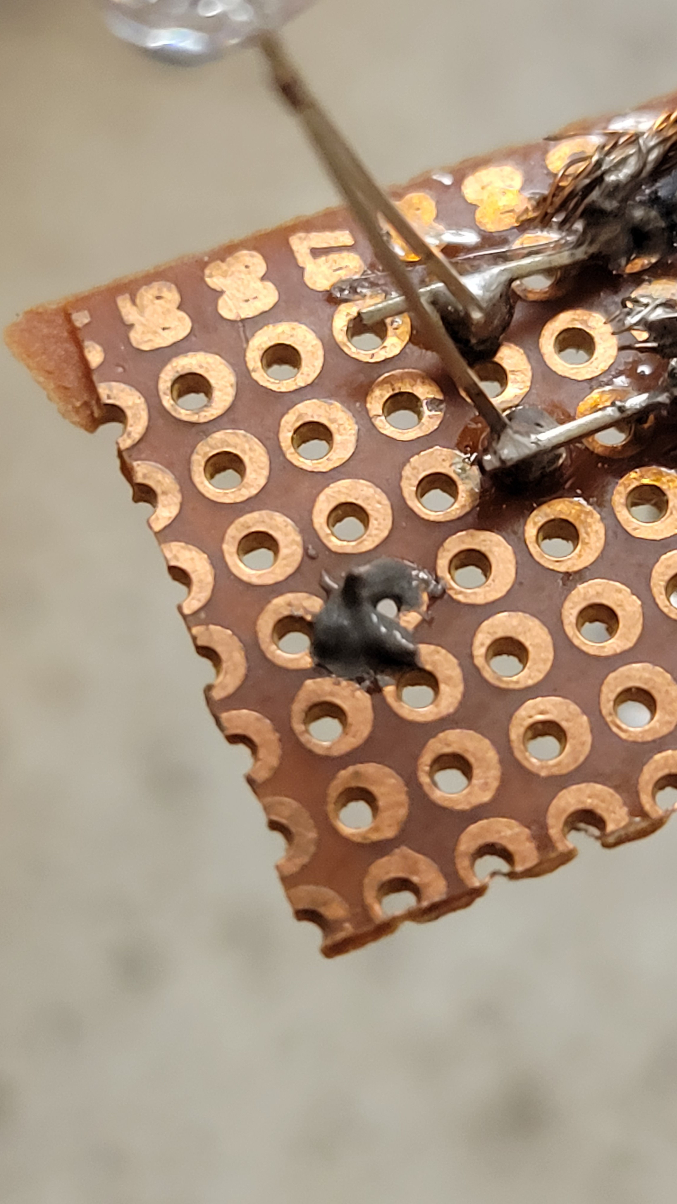
Oops, I got him all covered and hopefully not lost. Now I started my hot air gun, and it's become quite funny since the resistor started to swim inside the paste. Although it funny on demo, it won't be funny once it displaced on real PCB board. Maybe I should use slow air stream.
Lower air speed and 250°c done the job
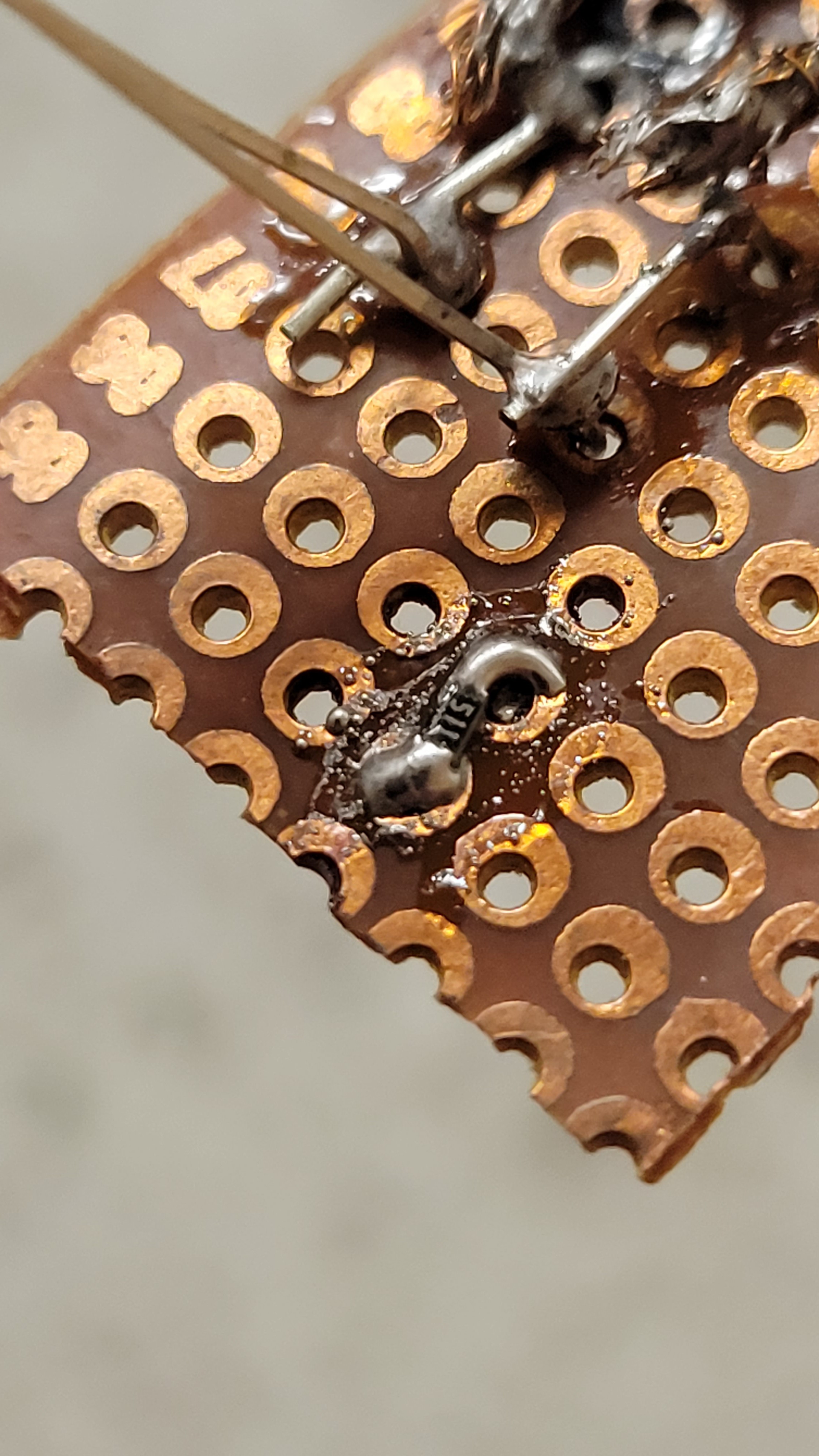
Not as pretty as I wanted to be but I think it will do for now.
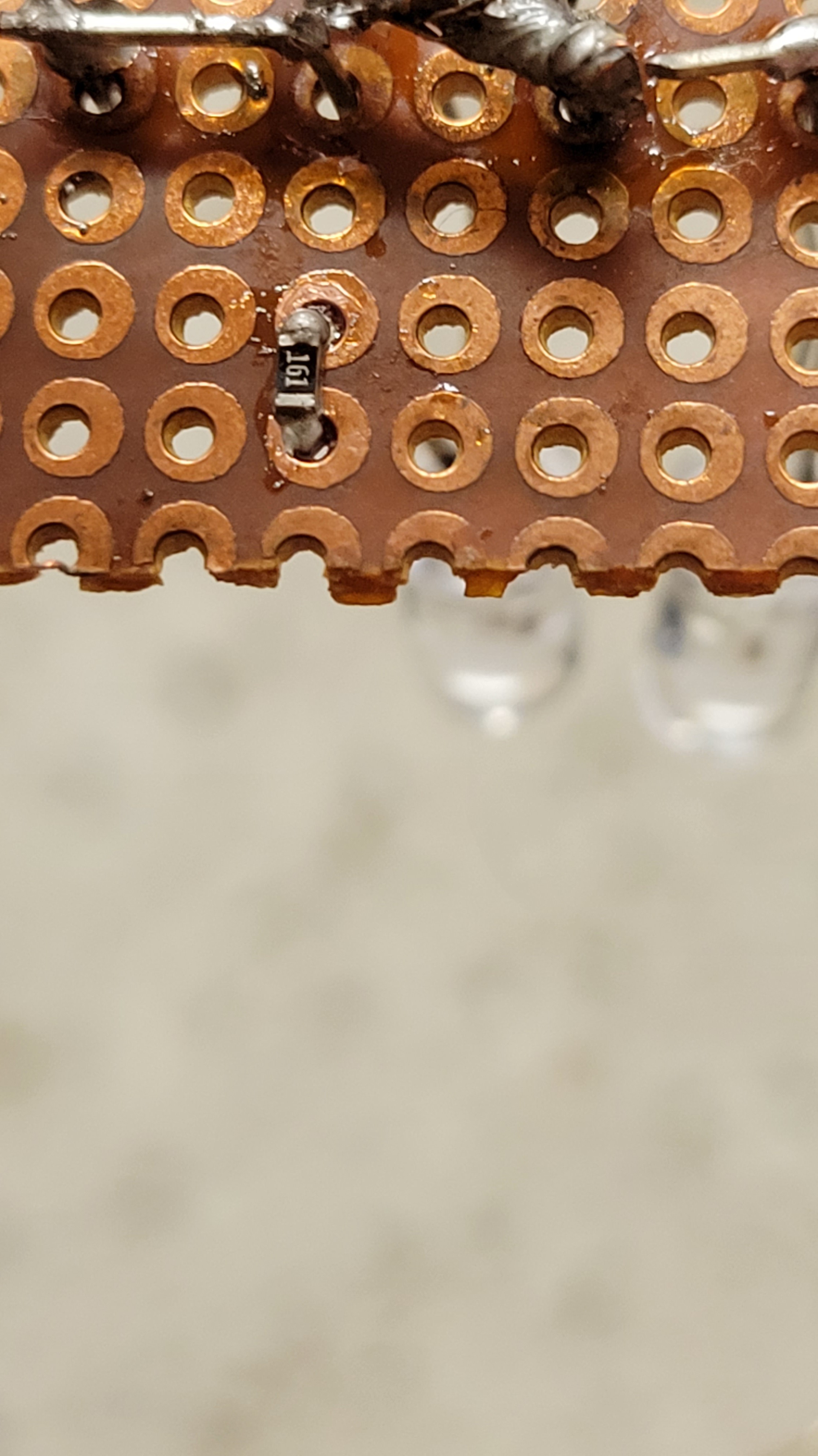
Take 2, less paste, wider air gun nozzle and I got much better result.
Let's try two simultaneously, if this goes well we can try the real thing.
Ok, sanity check ✅ let's put some components together just before the big mess...
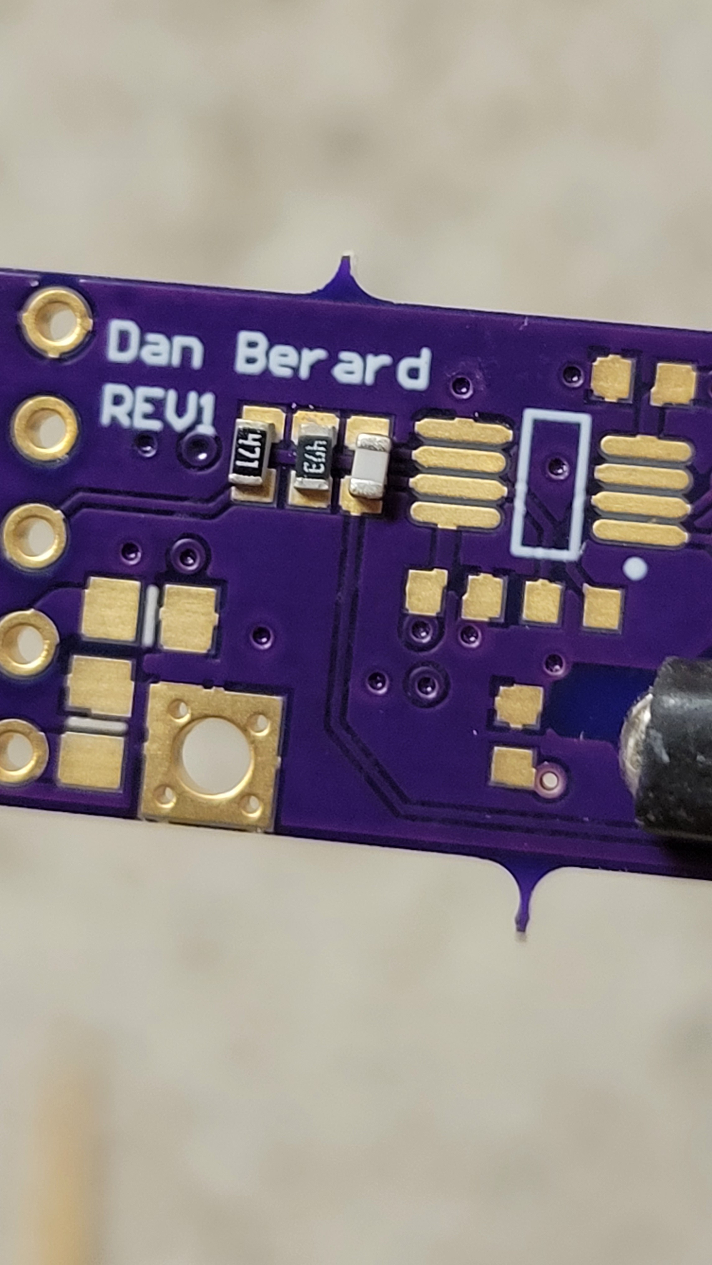
And soldering....
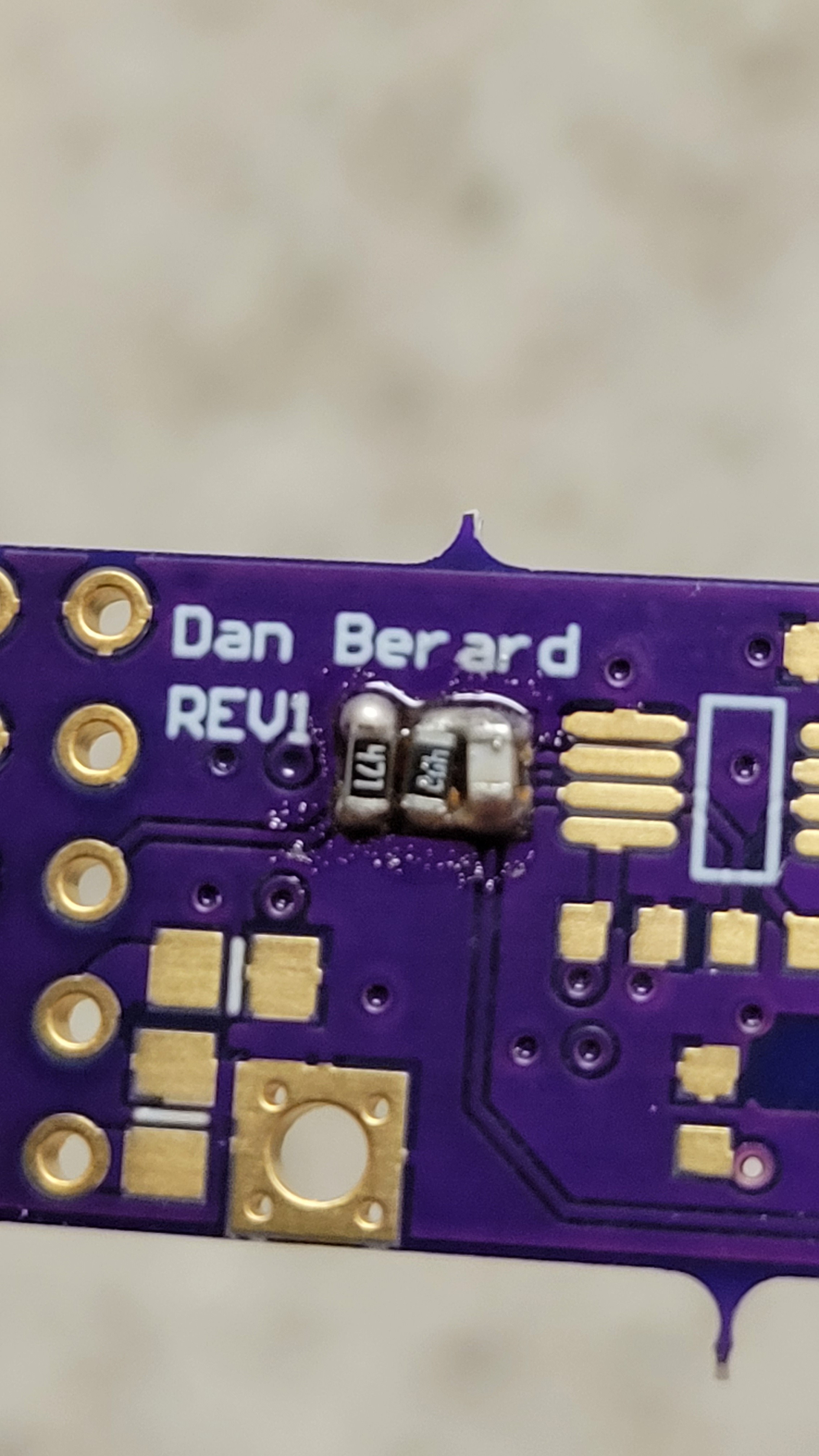
Not bad for first try... Oh, wait a minute I got resistors switched... The first one should be the 47K... Arrrr...
I took me two hours soldering and de-soldering to get to
Not bad but it's only half of the board... Alas!!!
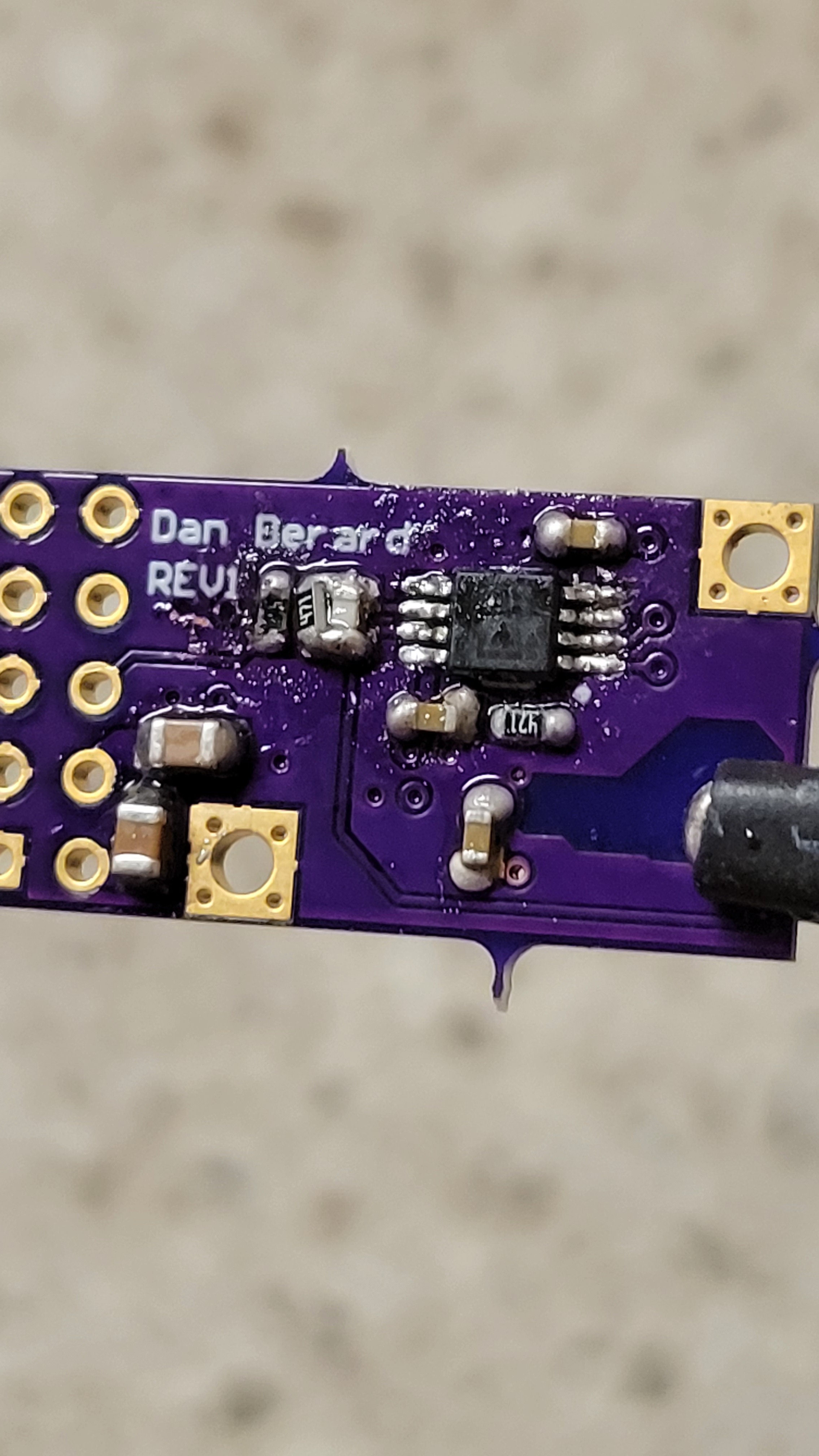
At this point we got only attenuator IC, I thought I would be a good idea to test it. We already know what shows be, we did it in the early stages of this project back then it was breadboard and single rail. Now we have a nice PCB and double rail for power. Instead of making new one we can decrease change pump from 12v to 5v. Easy....
It's just change one resistor for each rail. Positive changed to +4.5 but the negative is still on -12v. What?! Why?!
After few hours of poking each pin and trying to understand what is going on, it looks like it is broken.
It's quite annoying to go back and fix already working parts.
Discussions
Become a Hackaday.io Member
Create an account to leave a comment. Already have an account? Log In.