We have created nano scale probe using Tangsteen wire, but we have never glued it to active Quartz fork.
Once we have QFM, we could connect the electronics on PCBs, [PCBs makes it more mechanical and electrical stable].
After electronics done, we could connect the mechanical part and do the first experiment.
First thing first, Quartz Fork, it looks like an easy step but twice I've tried twice I got my Quarts fork filled with glue, I don't think it will do any good. On the second time I got idea to turn qfm upsidedown but now both qfm and syringe got in glue...
One interesting thing I've learned is to use a non-flexible 'helping hand' as it more rigid and has less movement.
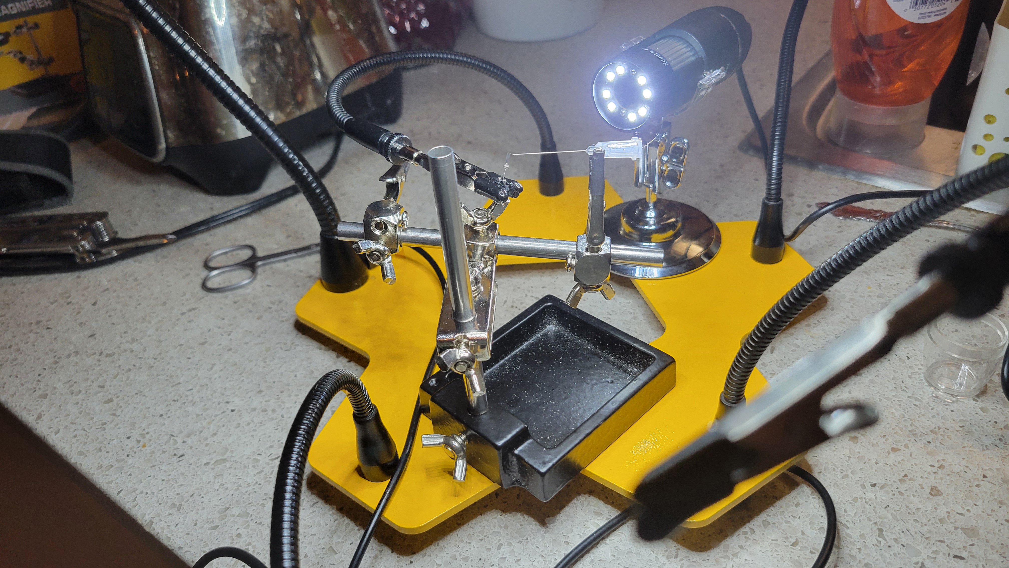
After successful gluing using syringe and microscope
 The next step was to etch a nano scale tip. After few hours of etching I got a feeling than I don't use Tangsteen wire after short google-seach I found out that I was sold some other wire
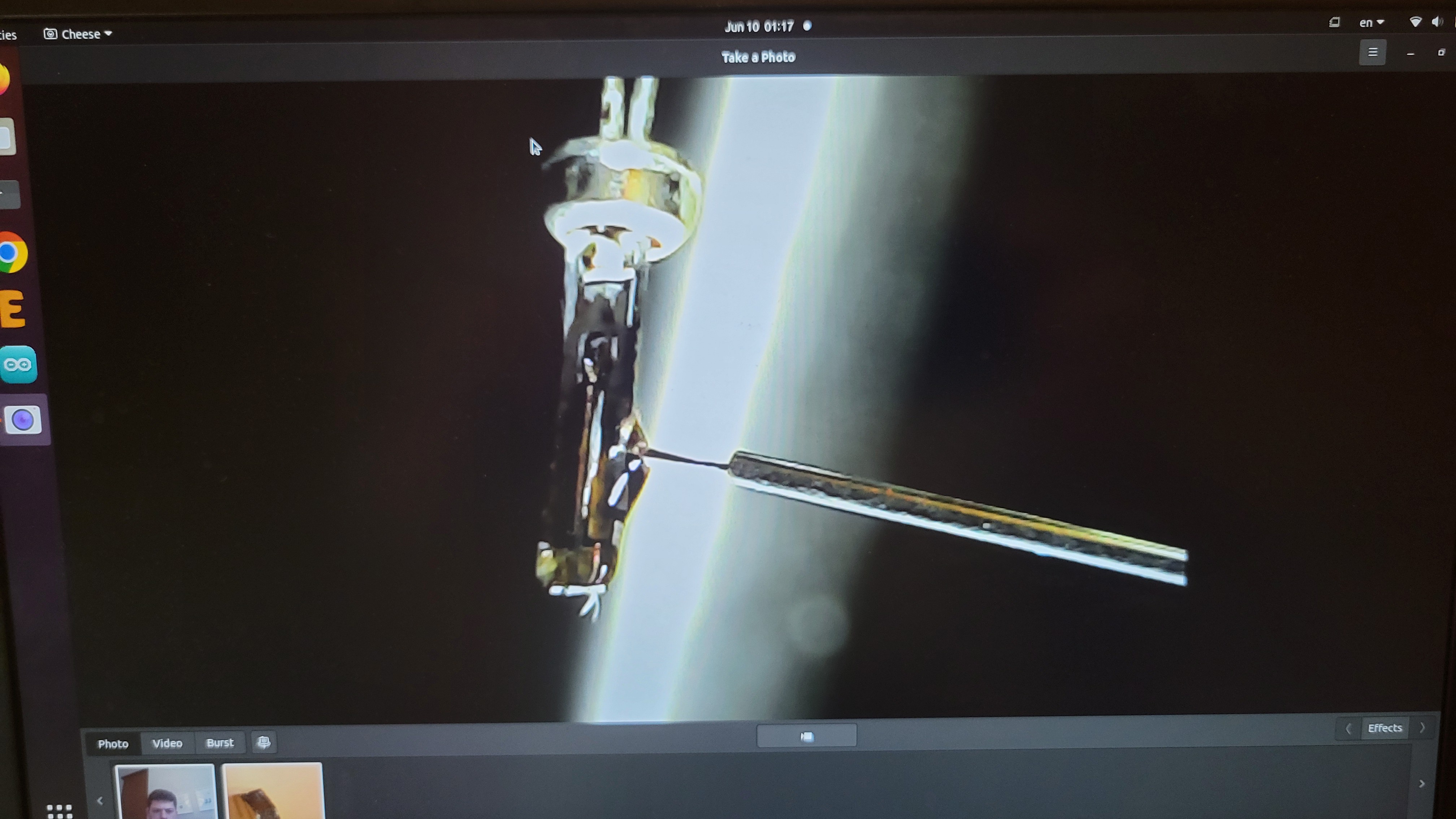
Got a new 0.1mm Tungsteen wire (I hope it Tungsteen) third time I scream :)
Managed to glue it right this time
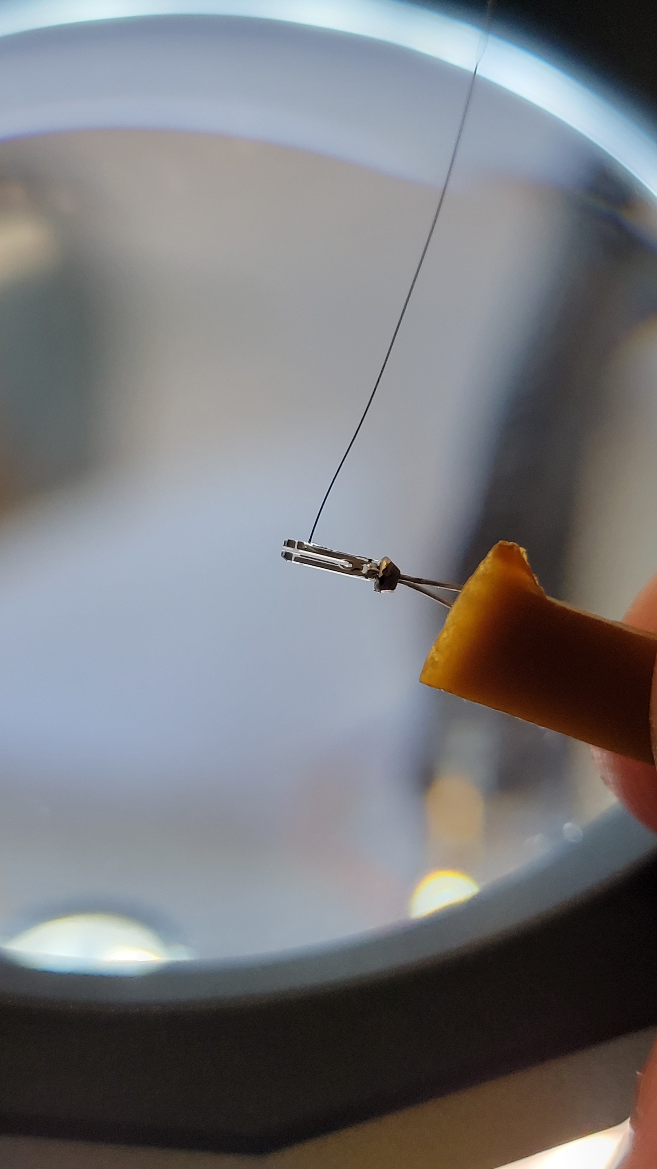
After etching it in NaOH solution we get
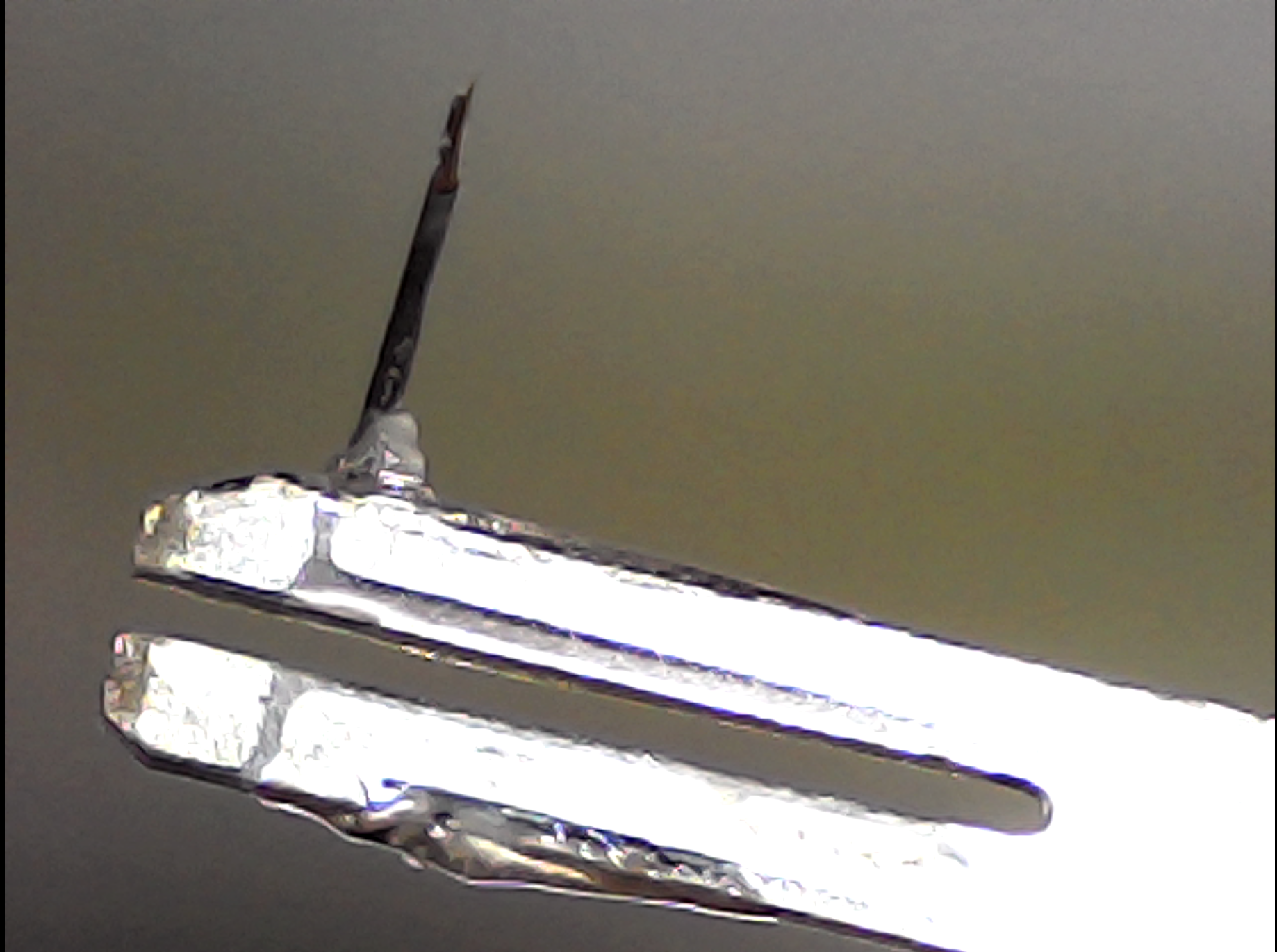
If we zoom in, we can see the tip
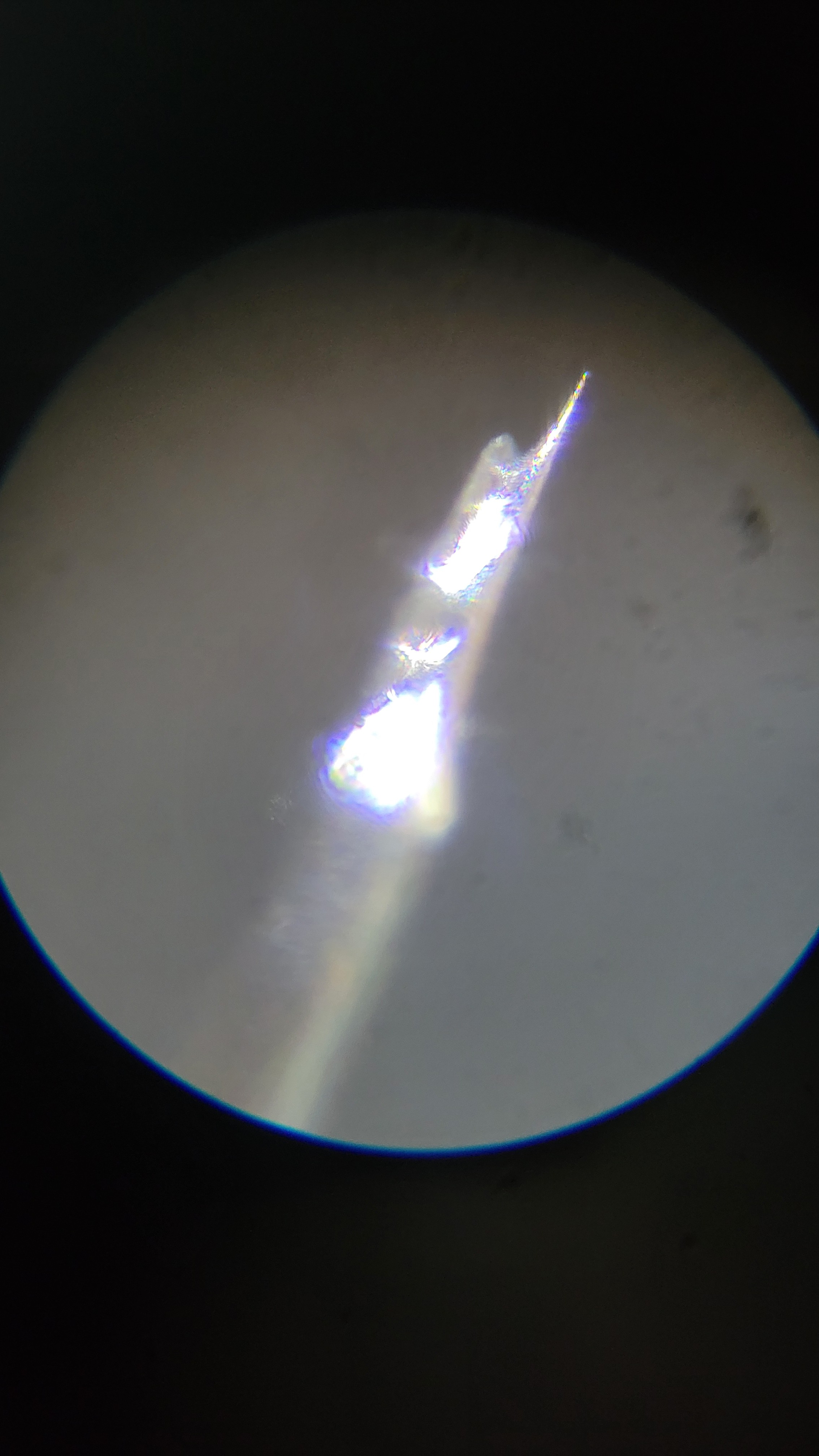
I don't know what I have done wrong to get this strange form but it's not bad for first time :)
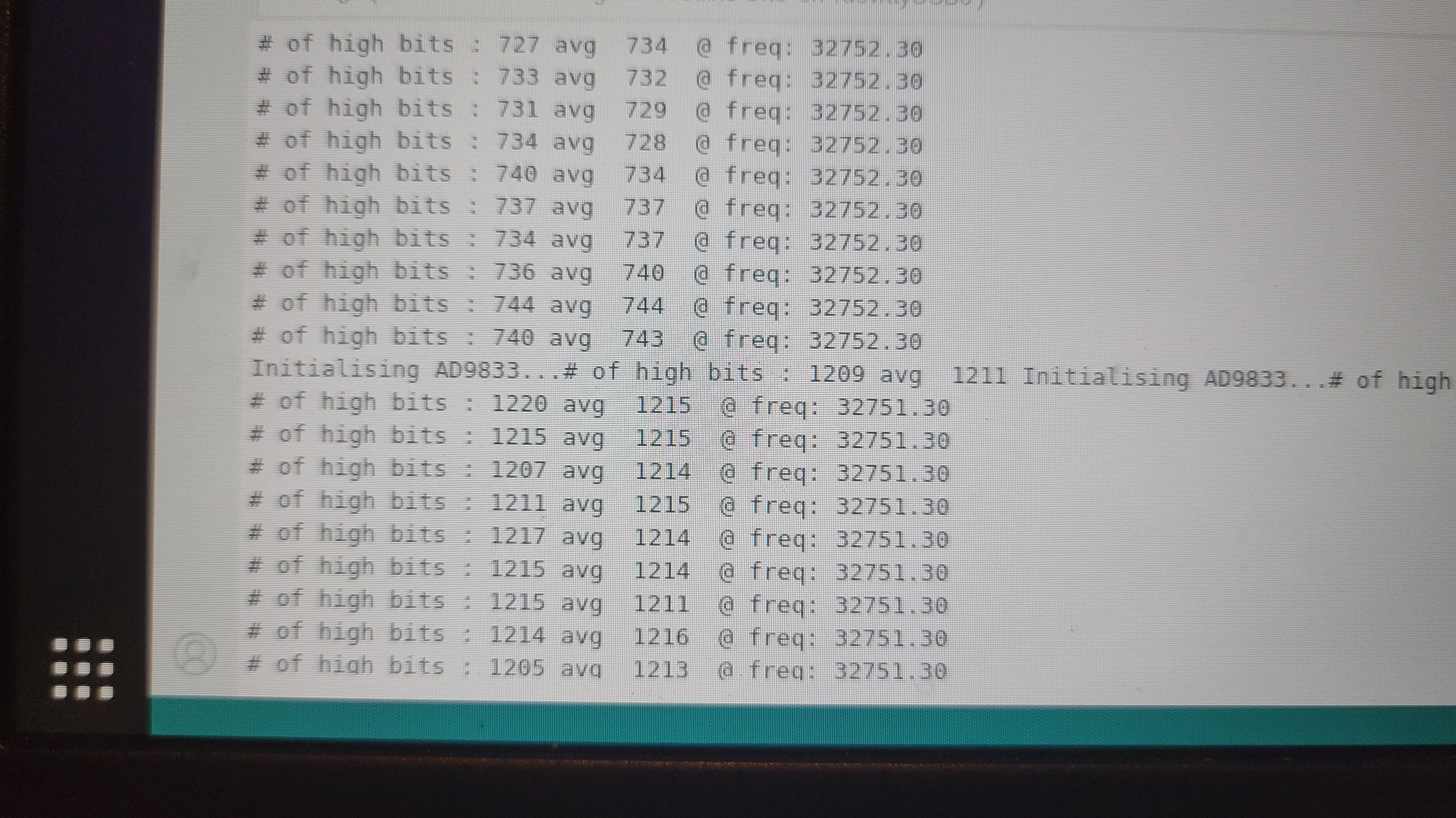
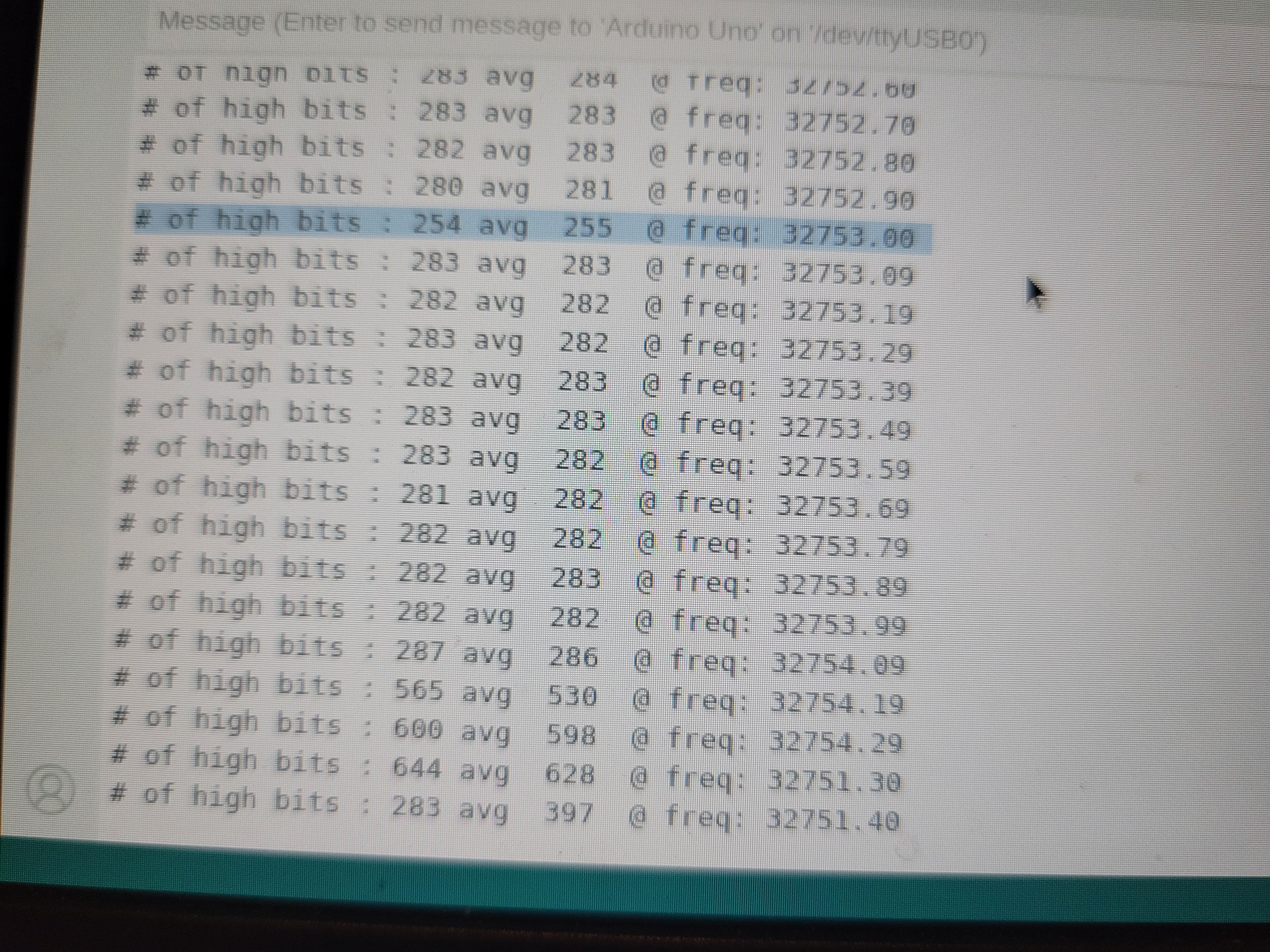
It's a frist time I am integrating data path from Arduino back to PC. The idea is to be able to measure frequency. After some minor changes (pullup resistor and sosftware chagnes) I was able to be able diffrentiate 1Hz quite easily. The output changes almost twice from 730 to 1200.
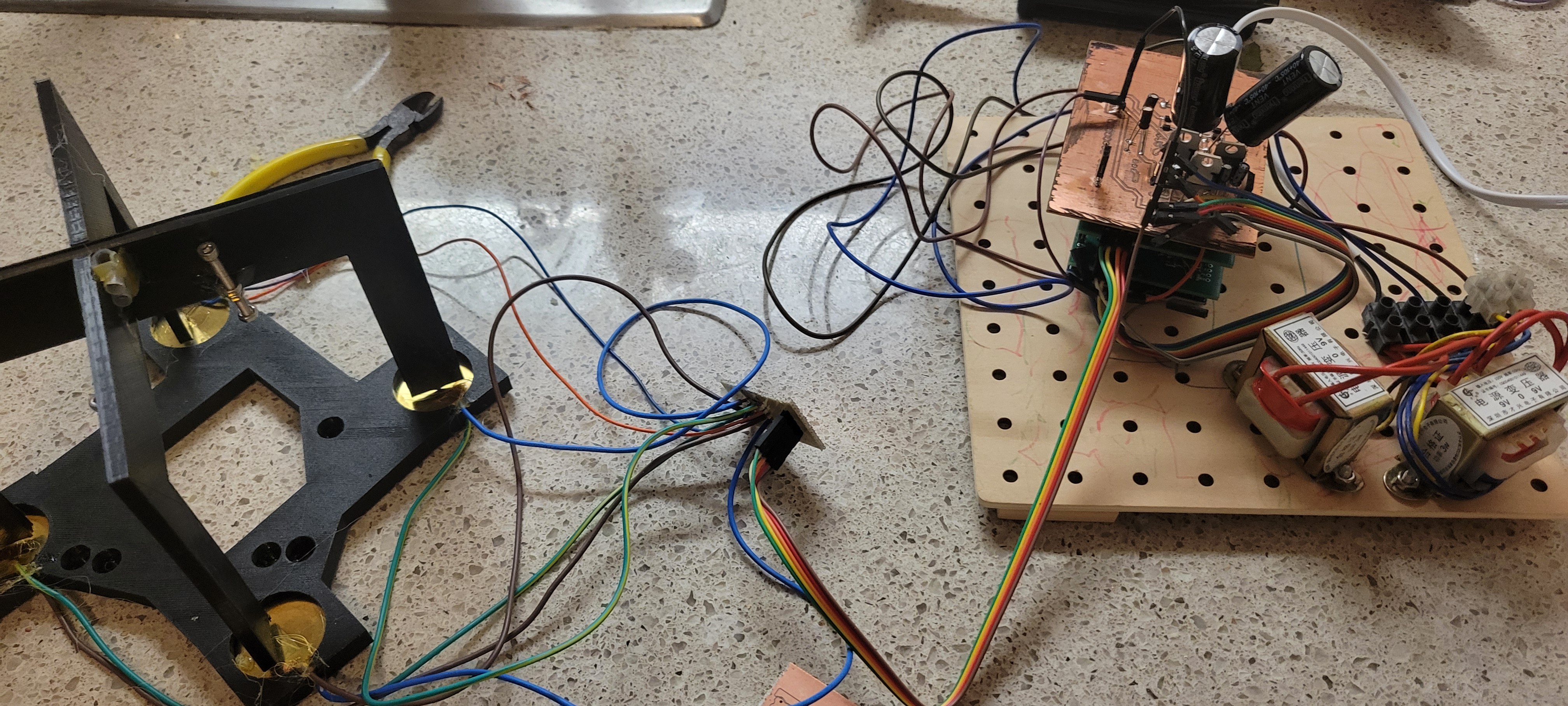
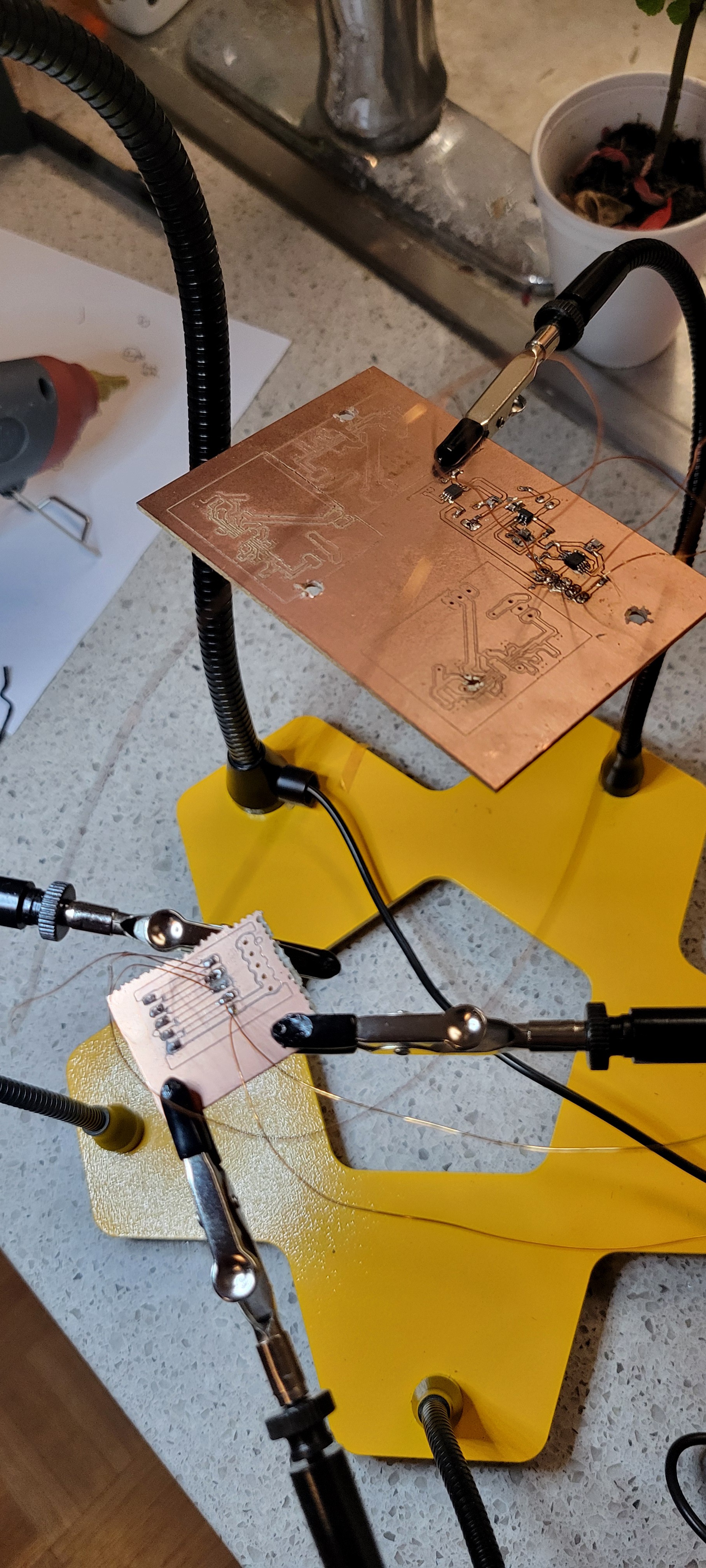
Now I am able to connect all boards together and get both frequency sweeper and 16vpp piezoelectric controller.
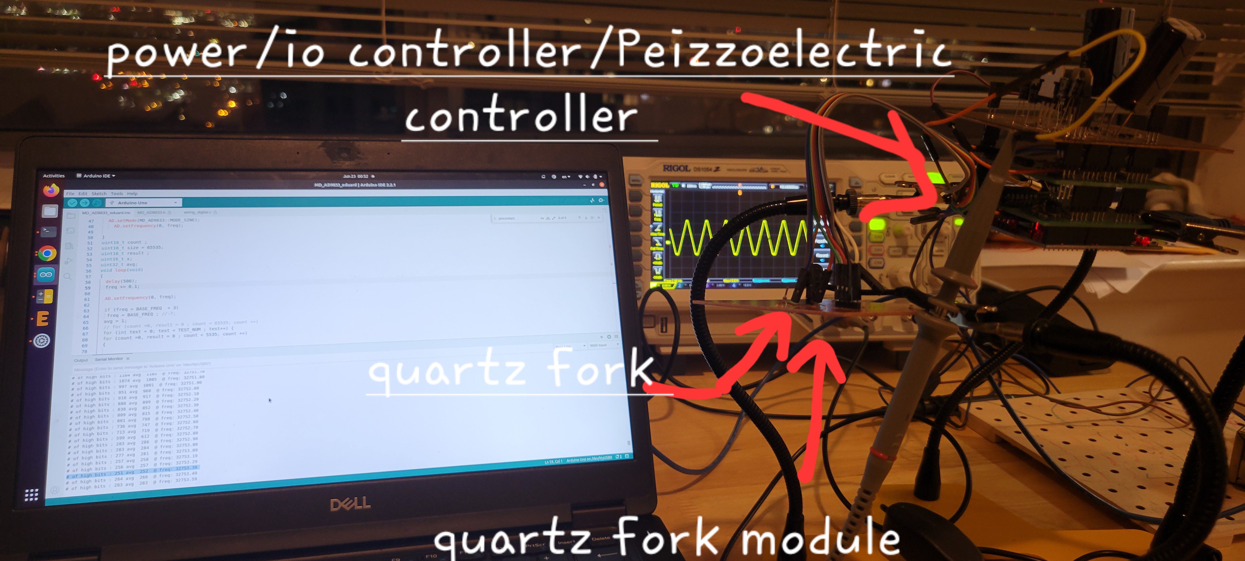
The next stage would connect it on top of mechanical stage and write software that could both change piezoelectric voltage and sample frequency in one simple software.
The coarse movement for now it's just made of standard screws and nuts connected with hot gun glue. In the future it's will be part of 3d printed frame
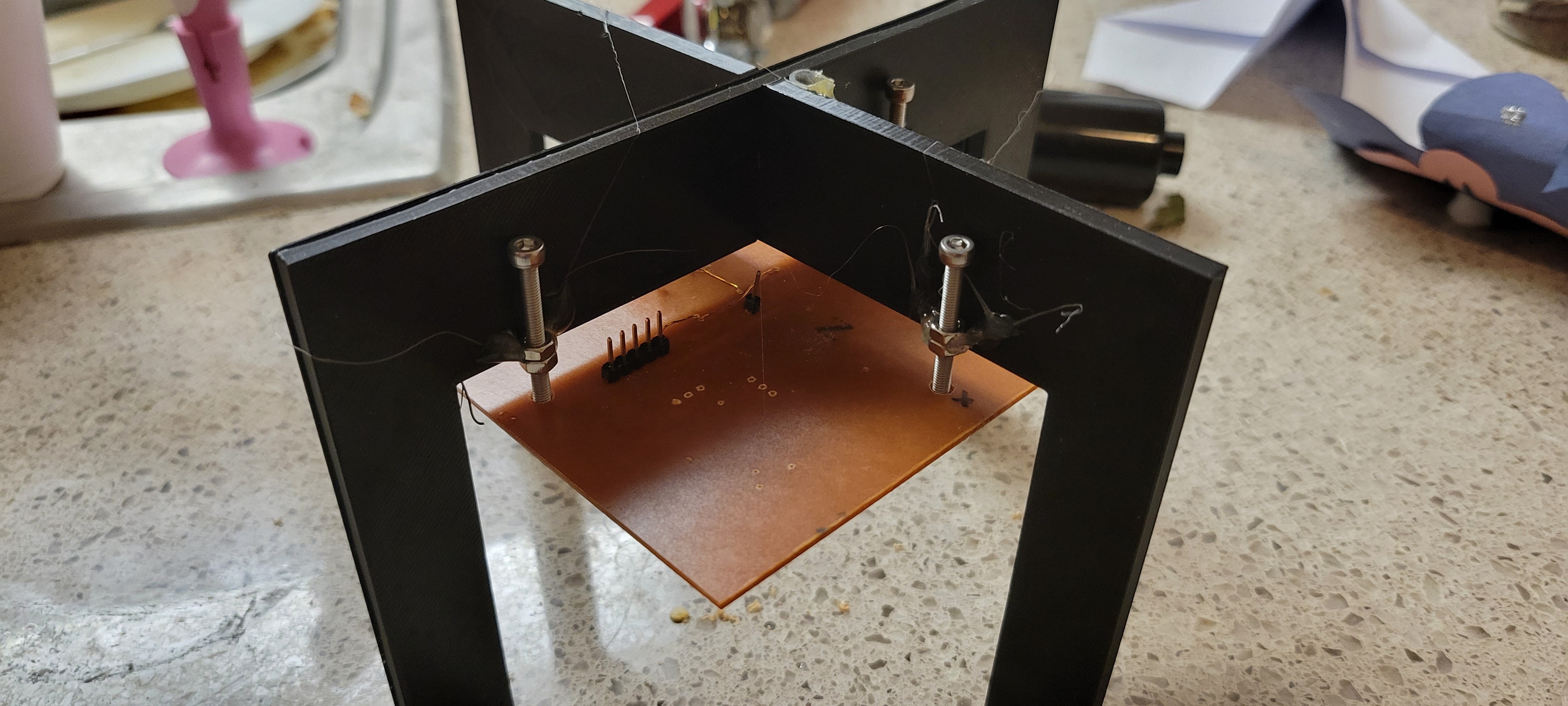
On the bottom of the quartz fork module is the quartz fork.(Not seen in the picture)
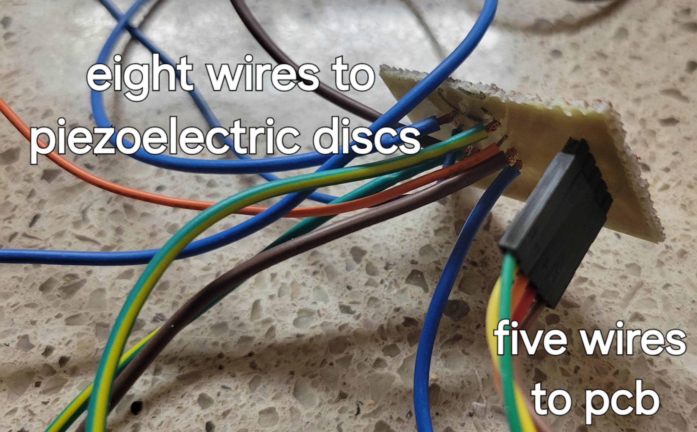
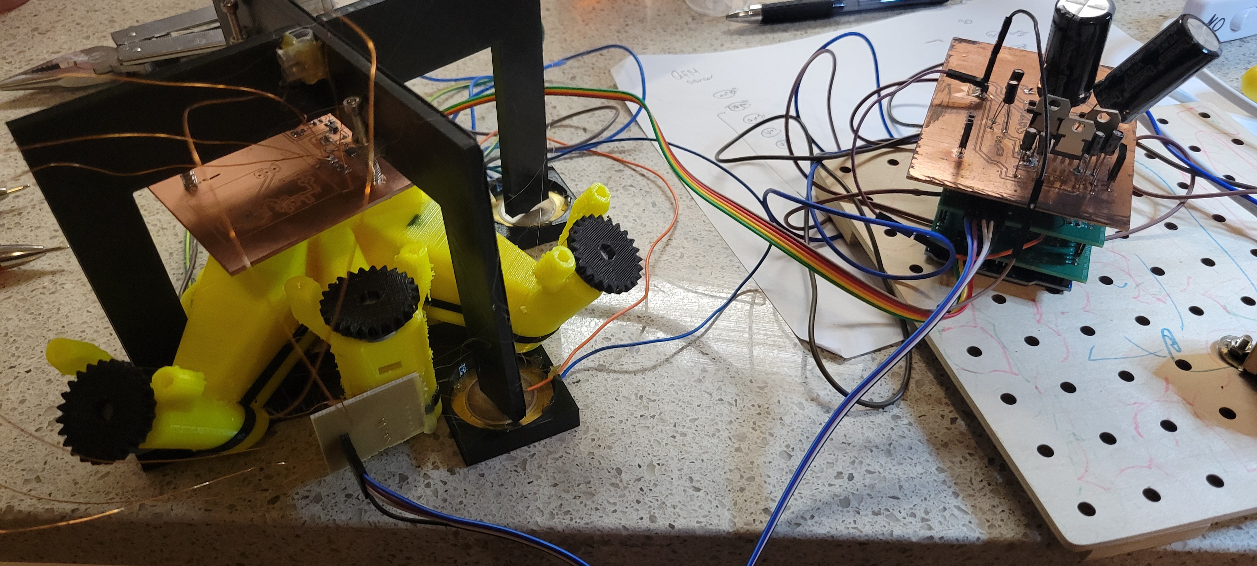
At some point I've realized that thinner wire must be used instead of breadboard jumper wires.
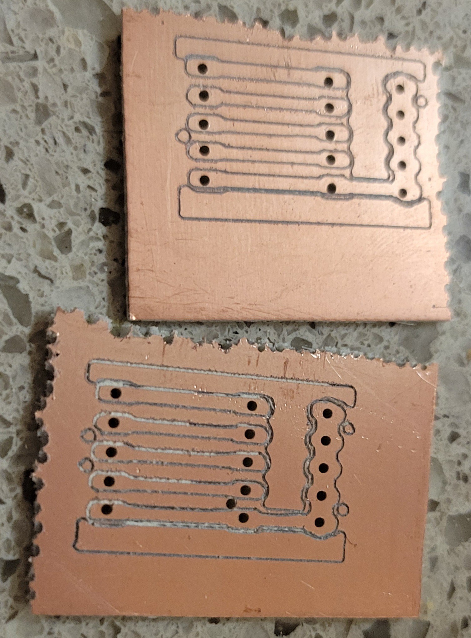
Plus, the eight wites of piezoelectric discs must be converted to five wires with all four ground connected. For this I made simple PCB converter.
Connecting everything now looks easier and stronger build.
Now, all together
Although this is a second video of toothpick dancing under the microscope. This time we use 10$ camera with long working disatnce. All component soldered to PCB instead of using breadboard. All components were tested and noise was reduced.
Another aspect is understanding of how much it will be able to move in real life. In other words how close we should place the sample in order to pick up the surface.
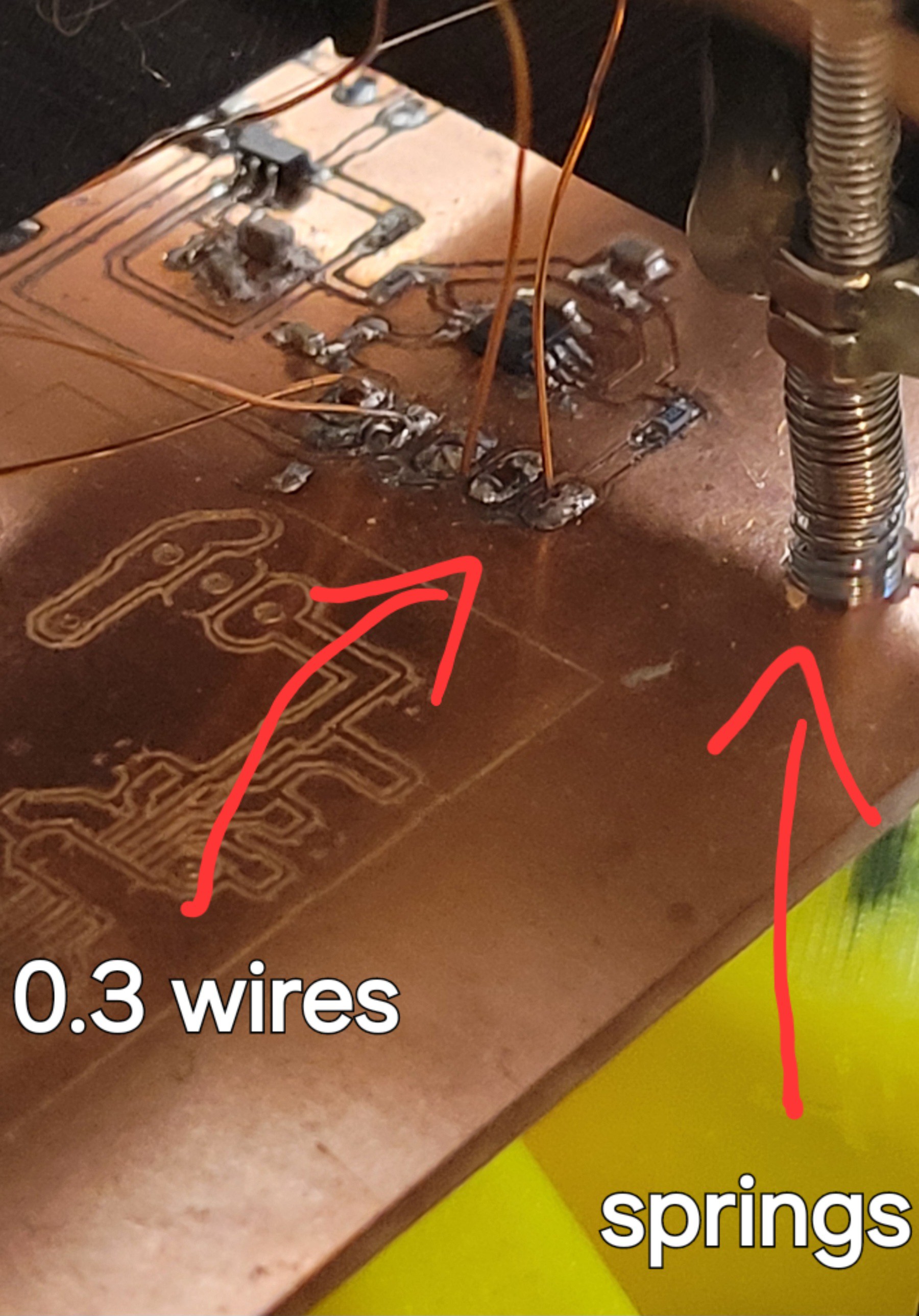
The next thing was adding copper 0.3mm wires instead of breadboard jumper wires. This way readings should less influenced by those wires.
Afterwards I've glued everything together and added springs to reduce movement
Here is the full microscope
One thing I didn't do is to add quartz fork with Tungsteen wire.
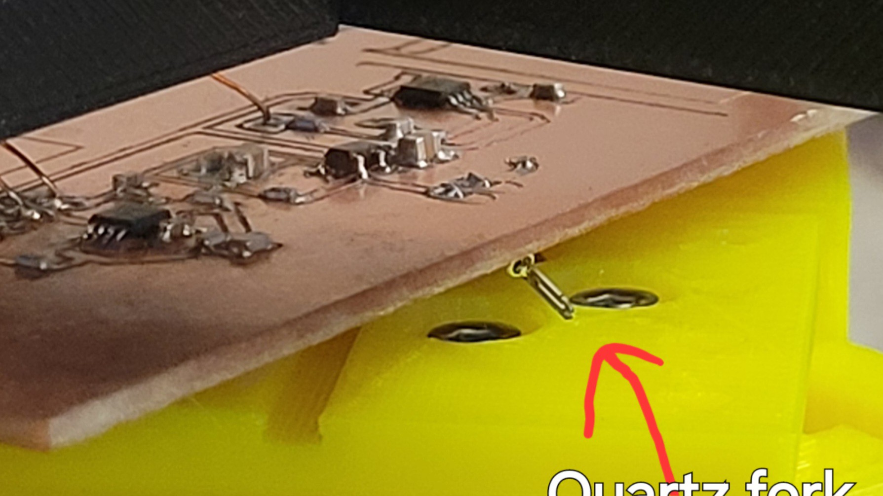
That's because I don't want to break/bend it. For now I will do the first steps with just quartz fork and once it works probe will be added as last step when scanning could be used.
---- THIS MINIMAL VIABLE PRODUCT. ----
Discussions
Become a Hackaday.io Member
Create an account to leave a comment. Already have an account? Log In.