I had no intention to make STM, there are many who done it before and much better than me but I have to do it to debug AFM. Or at least to know that the patterns I see are really from CD-ROMs' pits.
I've used AD9833 signal generator at 0 frequency and played with phase to get voltage from zero to 0.6 Volts. There was no via there so I had to solder to capacitor. Ugly but working.
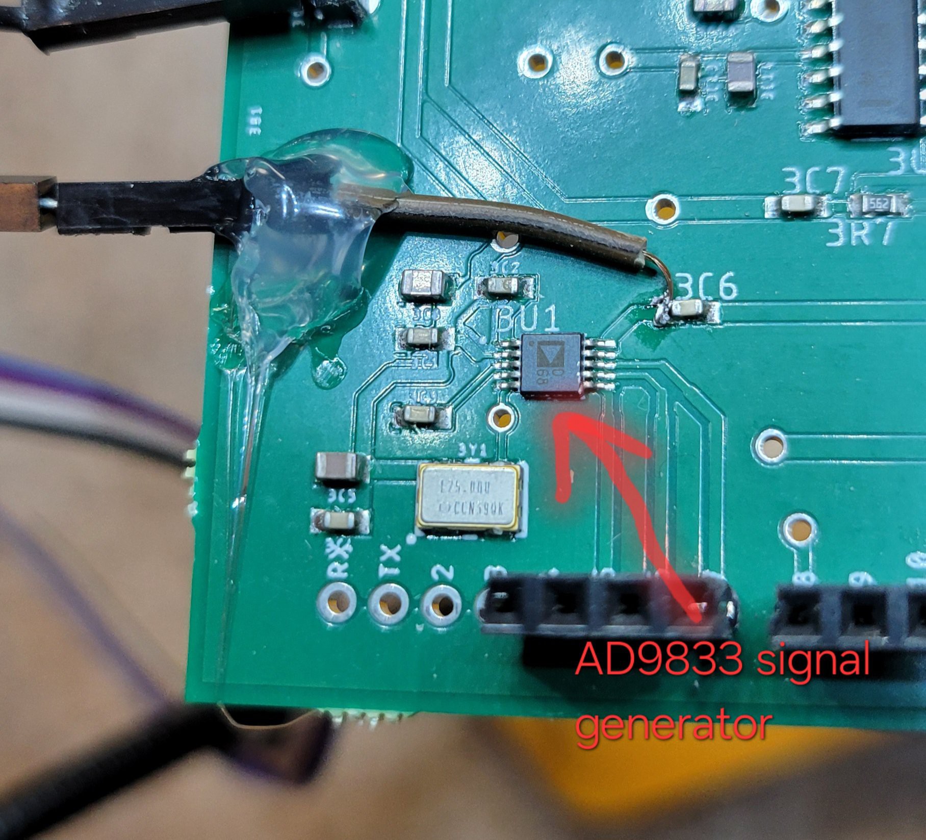
This output will be connected to the surface.
On the other side probe will be connected to USB connector (it's not really usb, just a holder for AFM tip). Output from op-amp will be connected to internal Arduino ADC A3 pin(pin A5 is for I2C). If everything will work we could get image with minimal hardware change.
Great news! I made the 'circuit' I've described earlier and it looks working. When I don't connect signal generator (AKA poor mans DAC) the reading gives something below 400. Readings are jumpy but it's alright simce I've not grounded everything there. When signal generator connected the readings are flat 1005 (I didn't investigate why this magic number but probably it my OpAmp getting into saturation).
Setting threshold to 500 could easily distinguish between touch and no touch.
I've connected wire to surface and make sharp tip from copper
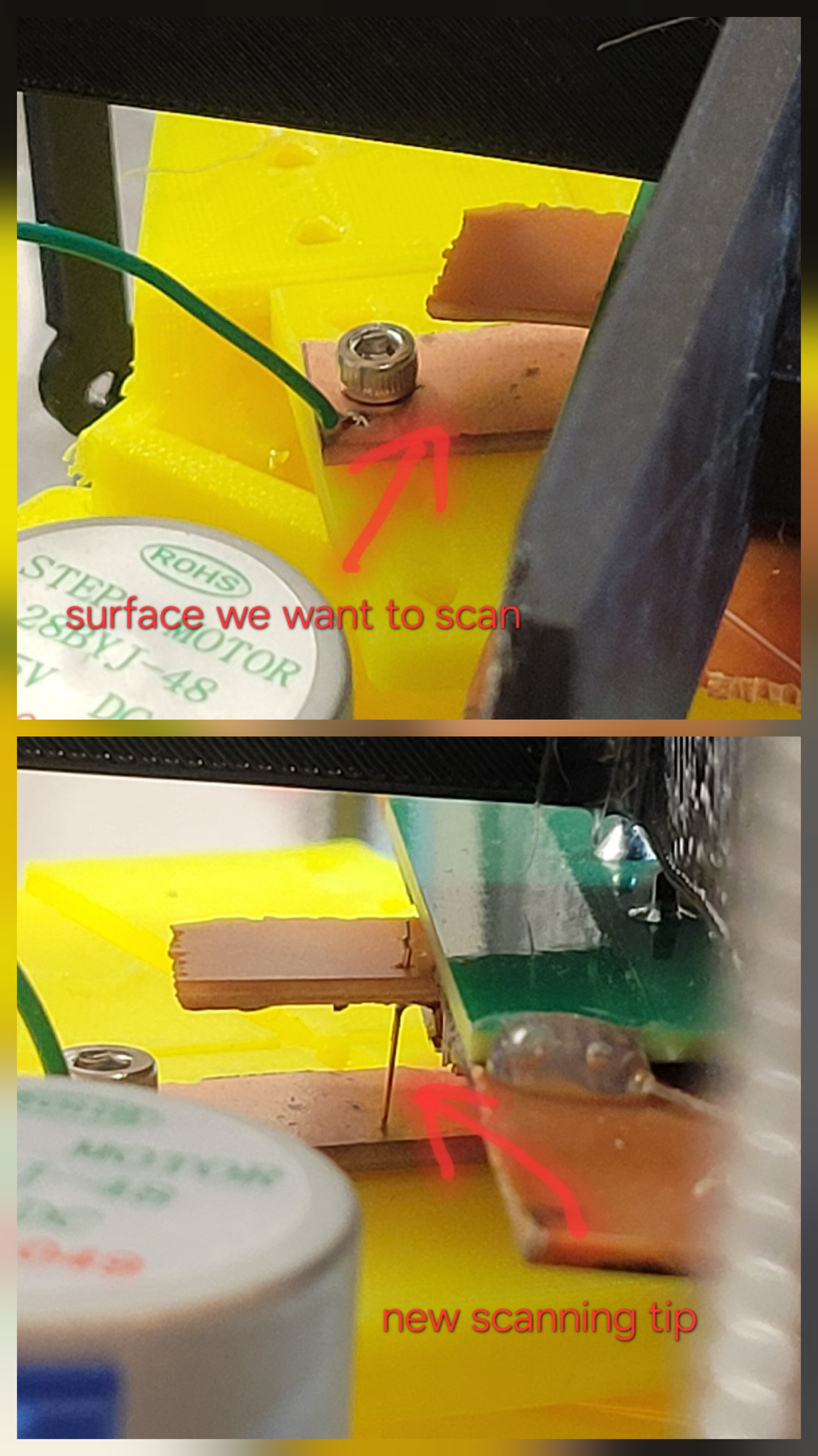
(Etched Tungsten is probably better but is so time consuming).
Started running 'approach' but everything stacked, just realized I've used A5 which is also used for I2C communication. Manual approach looks ok.
Changing A5 to A3 solved the issue. I was able to 'approach' and made few linear scans. It looks much more stable than AFM scanning.
There is another problem now. That surface gets out of the reach of the tip for some reason. I will try to reduce vertical hop size.
I've made some changes to vertical hop size, number of readings per sample (I have lots of noise and too lazy to build grounding enclosure) and changing threshold to 500. Now reading left to right and right to left seems stable. Now I should make an image. Hoping for the best.
Now I made separate python file for STM controller, so I can make images in simple way. Here is what I got from my first run:
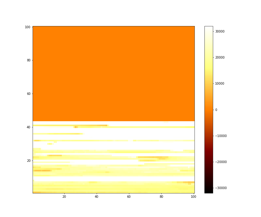
I see clusters so this is a good sign. (The white stripes are places tip couldn't reach sample anymore since it's not aligned well with tips's motion plane, I had to move micropostioner to re-align)
Another problem is that surface is not always align with tip movement. I've realized that the problem is that my mechanical system contains only three degrees of freedom XYZ. I need 5 degrees of freedom XYZ plus Roll and Pitch.
Another interesting observation is that now there's changes in height of one samples. In AFM changes were always of few samples.
It took me a while to find a way to connect Tungsten wire to copper (it doesn't like soldering) in simple way.
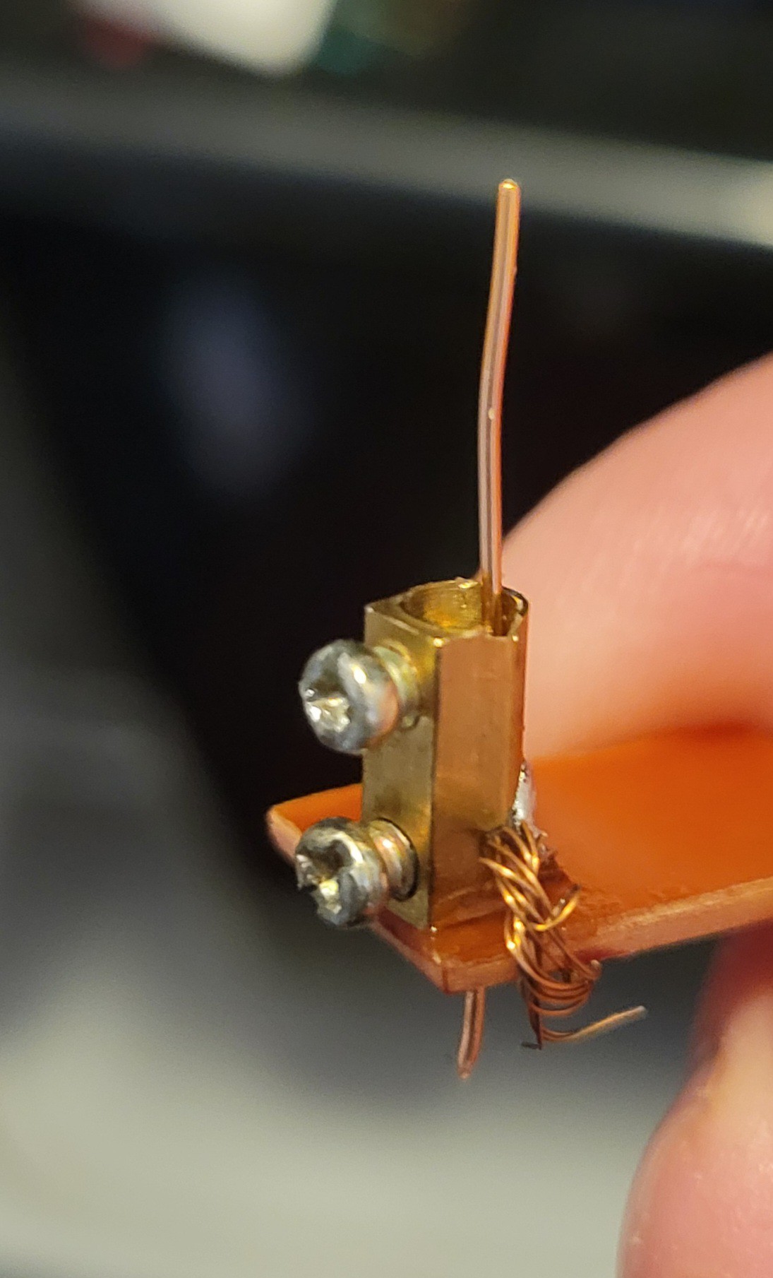
Now let's try it! Finger crossed 🤞
Discussions
Become a Hackaday.io Member
Create an account to leave a comment. Already have an account? Log In.