 Jesse Farrell
As mentioned in my earlier log, the last rejection test was a bit flawed. Here’s my second attempt. Unlike before there won’t be any AC signal injected on top the common mode, just a DC offset. This offset is supplied by an isolated lab bench PSU. See my test setup below.
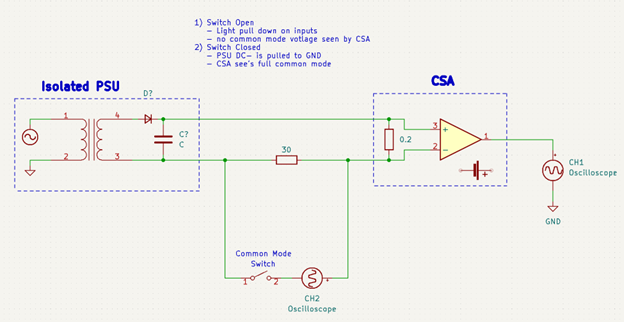
In this circuit the “Common Mode Switch” is what enables the common mode voltage. While this switch is open, a light pull-down in the CSA should essentially remove all common mode voltage. When the switch is closed (which I will do by clipping CH2 GND to DC-), the CSA will see the full common mode voltage riding on top of the 30ohm resistor. Here’s my actual setup….

None of my tools are particularly precise/accuracy so it’s somewhat the blind leading the blind when it comes to these results. Nevertheless, these results are valuable in a comparison to one another... Note that I calculated the expected current using the CH2 mean divided by the measured resistance of the 30 ohm load (29.2ohm).
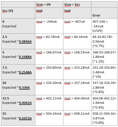
Ok so the error added by common mode voltage is less than ~1%, at approximately 286uA/Vcm. I’d call that a success.
Discussions
Become a Hackaday.io Member
Create an account to leave a comment. Already have an account? Log In.