I went back to my previus design. This time I got smarter. I've installed LTSpice simulator, much easier to change values (no more dead MOSFETs). Bought nice 100Mhz scope and high voltage probe. I was ready...

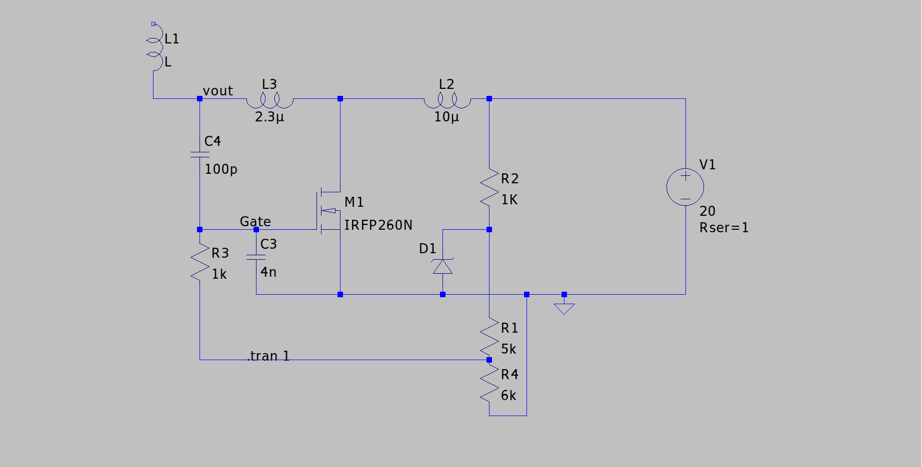
I've started with making Tesla coil schematic on LTSpice. It much easier to understand this circuit in 'clean' conditions.
First part is easy, D1 zener diode and R1,R4 resistors are simple voltage regulator for 15v.
Second part is the oscillating circuit L3,C4/C3. Since C4 is much smaller than C3 (or MOSFET's gate), the frequency calculated from L3 and C4. C3/C4 Makes a voltage divider, thus feedback to the gate.
The L2 is not important as long as it between half of L3 and 10x of L3. But in reality L3 can be one of few values and it's related to L2, wrong L3 value leads to low performance. (low voltage on Vout)
The third and the tricky part is L1, it's not self resonant coil but a 1/4 wave resonator.
There is a nice video I made about it
PCB of this Tesla coil can be found on:
Discussions
Become a Hackaday.io Member
Create an account to leave a comment. Already have an account? Log In.