Boz
Boz-
Firmware updated
05/29/2015 at 04:30 • 0 commentsI have updated the firmware to github.
The firmware is simply all the hardware parts working with a simple menu to scan barcodes, scan RFID tags and do some basic wifi comms which should be enough for you guys to run with.
The development from this point on gets very specific to my clients manufacturing and operational requirements and it wont really make much sense to publish it, it is not that I don't want to it is just that the MRP program it is interfacing to is like most production software not open source and not publicly documented.
There are several paths open to people who want to build on this project, I am thinking that the most suitable if you do not want to build your own server is to use one of the many MQTT implementations, the ESP8266 has several flavours of client for this and lots of back-end broker services are documented using it.
I am in the process of writing an open MRP system for another client, however this has a very open ended timetable as other projects allow, I will be porting the data collection terminal to it sometime down the line though if people want to keep updated via my web-site.
-
Hardware complete and tested
04/28/2015 at 00:59 • 0 commentsThe final version of the hardware using the new RFID card is now working. Circuit and PCB are available on the EasyEDA site
Last minute changes include using filter glass to enhance the performance of the bar-code scanner, I tried both samples of commercial filter glass ($4 a piece!) but the red transparent films used for hobby and crafts you get off eBay seem to do just as good a job (I cannot measure the filter but I guess it hits that 625nm sweet spot for the CCD just as sweet. I have also updated the MPU to the PIC32MX250 as there are some USB boot loaders already available for this.
The RC522 RFID chip already has some public domain C++ libraries and seems easy to use (though a bit complex for what I need) with the move to 13Mhz I can now program the SSID, password and encryption keys directly into the RFID tags so security is as good as it gets and much better than I actually require due to other factors.
First unit is still a collection of drivers and test procedures which I will eventually put on git hub (I don't really use git-hub properly. one day I will get around to learning it but for now its a place to throw releases when I think I've hit a milestone)
Pictures below.
![]()
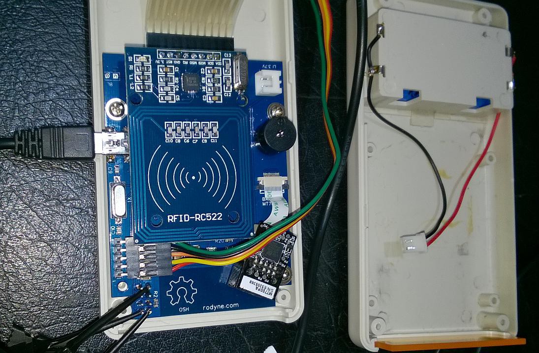
First picture showing the unit with the RFID card fitted. The ESP-01 module is right at the bottom and under the main PCB, bar-code reader is about 1cm from antenna but does not seem to affect performance.
![]()
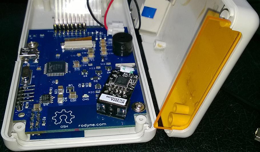
Second picture (above) is with the RFID removed exposing the guts of the unit. ESP-01 module can be seen flush with top of case (PCB is screwed to top of case with LCD mounted on the back)
Last picture
![]()
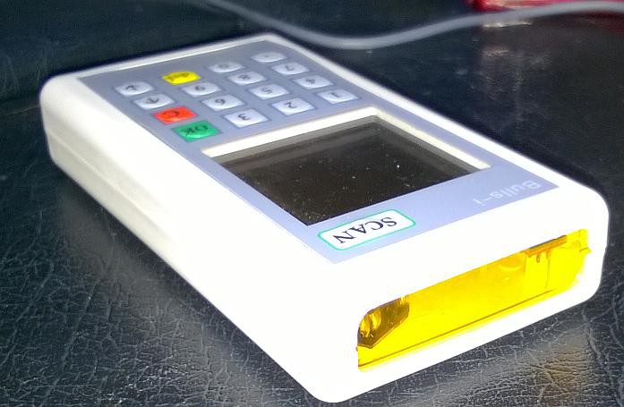
I am getting some cases cut in black ABS, the grey is so 1980's in most peoples opinion! The window is actually more orange but it filters some of the flash colour.
Note all the parts work and have been tested individually, the next step is finish off programming and to get 30 boards assembled and into the hands of my hopefully eager users!
-
Last minute changes
04/11/2015 at 08:12 • 0 commentsJust as I get the prototype working, we have decided to move from the 125khz EM4100 RFID to the 13.7Mhz Mitac RFID standard. the reason is two fold
- We wanted to simplify configuration and improve security by having the SSID, password and host in the tag as opposed to three different bar-codes and also have part of the encryption key in the RFID tag. That means one swipe of the tag can configure the terminal. The RFID tags have 700bytes of storage will be secret sauce though)
- The main client is moving to this standard and away from EM4100
There is actually a plus to this in that you can get per-assembled RFID readers for about $3 (I actually just bought 50 RC522 readers off aliexpress for $132 including delivery - how do they even do that!) the new readers are SPI bus and there are loads of libraries already available in the Arduino community.
5 of the new PCB's are being made and hand assembled at smart-prototyping at a cost of $40 each should have them returned in a week or two.
I have also ordered some filter glass as opposed to the plain glass, this should improve the performance of the bar-code reader and block out the inside PCB to pesky users, should also make it all look a bit more professional.
All the changes will require a fairly big re-write so while I am about it I am also going to try and get the USB boot-loader working, there is code for the AVR dude programmer and PIC32/Chipkit system which I am hoping to be able to modify.
This is my busiest time of the year supporting several wineries during their vintage, it is now coming to an end and should give the time I need to finish everything.
Note the PCB and schematic have been updated to this new version of RFID, the previous version is still available if you search my projects on EasyEDA
-
Latest update
02/14/2015 at 20:35 • 0 commentsLatest board all seems to work :-)
The only bad news for me is that using a single 14500 3.7V 1200mAH AA battery instead of 2xHiMH batteries will effectively half the battery life (probably less as popular opinion seems to say these type of batteries exaggerate their mAH figures by about 50%) , though I'm happily still getting several days use during my testing, As I have effectively had the cases already made I am restricted to using an AA sized battery for this version, shame as there are some nice 2000mAH ones out there for less.
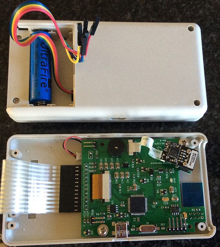
Picture below of the prototype, as you can see it is very low density and I have widened the spacings between most components to make it more hand solder friendly.
![]()
The wires sticking out are the ICSP programming cable which wont be in the normal version, luckily they fold under the battery cover for testing.
The ESP-01 (ESP8266) module fits perfectly at the top, away from all obstructions. the reason I chose the ESP-01 over the SMT versions of it was because I can program and test the firmware and module before soldering as my opinion of the quality of this unit is still not 100% I am using the V0.9.5.0 firmware which has V2.0 AT Command set. I will put this firmware bin file along with the documentation and on github once I'm happy it is at least as stable as the previous version.
Also note that as we power on the ESP8266 only to send queries we have to wait for the connection to establish each time so there is about a 2-4 second pause before the query can get processed (the SQL part to run several queries and return the results only takes 100mS or so) this is not really that noticeable to the user and has many advantages for me as it completely removes power to the ESP8266 effectively starting from a power on reset each time so we shouldn't get any cumulative stability problems introduced and power consumption is nil when we are not communicating. Same goes for the barcode scanner.
I have cut away a side hole for the USB connector which is a little messy.
Note there is a big whoops as I must have used the new sandbox version of EasyEDA to do my latest PCB routing as it does not show in the current link. unfortunately there is no backward compatibility with the old version but hopefully by the time you read this Dillon (the writer of the software) will have updated EasyEDA
(If not use http://sandbox.easyeda.com/project_view_Data-Entry-Terminal_neKEWQ8qI.htm )
You can also order a PCB from them (and help finance the project) by clicking on their shopping cart, the PCB's are made by seed studio and are really good quality) you can also fork off the PCB for editing and/or download the gerbers from here.
I have used the prototype and conducted a real life end-to-end test already ie
1. Scanned a barcode from a job sheet
2. Sent query via wifi to server and had server parse the query and return the details of the job
3. Updated the job status by selecting from a menu item
4. Send query via wifi to update job status and logs
This proves the concept is sound. There is also a blog post on the higher level stuff at my web site http://rodyne.com/?p=611
Note: I have not gotten around to testing the RFID, though this all worked fine in older prototypes so I don't expect any problems.
-
Hardware Finalised?
01/16/2015 at 09:09 • 0 commentsSo I have now settled on the 3.7V LiPo version which seems to have much less instability than the HiMH and I am cautiously optimistic that this is the final version :-)
The circuit and PCB have been updated and I have put a quick write up on the hardware and the progress on the software on my web site which I will copy over here in the next few days.
-
Wifi and Boost Converter
11/29/2014 at 09:09 • 0 commentsAfter several days of cussing and pulling out hair I have finally figured the problem with the power and wifi.
The NCP1421 works OK but cannot handle the sudden load of 250mA+ put on it by the ESP8266 wifi quick enough to prevent a brown out on the other parts of the circuit. As I will be switching power off and on the ESP8266 every time this is a problem. I tried putting capacitors on the Vcc up to 1500uf but it was getting a bit ridiculous so I thought I would try and stop the brown out by isolating the CPU/LCD 3.3V behind a diode (D1)/capacitor (c6) which will charge and buffer Vcc (PIC+LCD=24mA when not in sleep) and when the sudden drop occurs the schottky diode (d1) will not conduct and (hopefully and with careful selection) C6 will hold Vcc for the few milliseconds until the power stabilises.
As this is more a hack than a design I have also reverted to an old design using a LiPo 3.7V cell, both boards will be produced simultaneously so I can work a bit quicker as its getting toward XMAS I've updated the details on my website here
-
ESP2866 Failures and delays
11/24/2014 at 09:48 • 0 commentsMan this module sucks, it is so not ready for any project where you expect to solder it in and work. I know there is a lot of work going into getting it reliable but for now I'm seriously thinking of ditching it and going back to the lower spec (but reliable and useable) USR module I originally used. I will give it one more try to get it working.
I think I know the boost converter problem, basically the WIFI module wants 250mA on power on and I had the wrong size inductor in the boost converter to give this, dropped the value from 10uH to 5.6uH and much better now, though still not happy with a 250mA surge as I have had to pop in some big caps and the boost converter may not start at the end of its charge. Lets see!
I will update the BOM and circuit once I get through the wifi nastiness I'm having. Maybe at some future date someone will produce reliable hardware and firmware for the ESP8266 but for now early adopters beware!
-
USB Added
11/10/2014 at 20:35 • 0 commentsAfter a few private emails I have changed the MPU to the PIC32MX2xx and have added a USB port, the reasons being that
1. We can now support a USB bootloader and possibly some of the Arduino like pic32 environments like the chipkit
2. I can add a small NiMH battery charger circuit to recharge the AA cells via the usb.
The original prototype way back used a bigger chip and supported USB but all were removed in the simplification that followed. I've decided to risk adding it to the new PCB for completeness.
The new circuit and board have been updated to Rev5 for anyone interested so you can check out the changes which are:
1. Changed from PIC32MX1xx to PIC32MX2xx and added USB. 4 pins are lost due to USB support on this chip so I have had a bit of a shuffle around of the pins and removed the LCD_RESET which was not really necessary IMHO. K5, K6 and K7 have also been displaced and the scan/power on is only used for powering on the boost converter now (though I was toying with connecting it to the reset MCLR pin for a soft reset)
2. Added a charger circuit. note the charger circuit is pretty base as I will need to experiment with resistor and/or pulse settings to ensure safe charging, by default charging is off by setting the gate of the FET high, the idea is when I detect USB power (VUSB) then I will turn on the gate by setting it low for 5 seconds, turn it back off then check the voltage, this will repeat until I see the correct voltages on VBat (I put a resistor divider here but then realised the mav battery volts will always be less than 3.3V so really this is not required.
3. I have added a FET in the WiFi power line, I should have left this in from the last version but was deceived by the ESP8266 chip enable. There are a couple of big caps here, I will experiment with the values and/or if they are required (the ESP8266 has a bit of a surge voltage on transmit and power on) by default on power up the wifi is off, I will power it on -> send -> receive -> power off hopefully in a few seconds so each time it will boot from cold and hopefully get around some of the issues others are having with the firmware/quality of these devices.
As a note to self I will not solder in a wifi module until I test it connects and sends. I'm hoping the quality will improve as more manufacturers make these if not I will add the ESP8266 chip directly onto the circuit. This is a bit too much of a step at the moment as I still do not have all the time I wish on this project due to other commitments (ce'st la vie!)
4. I have removed the MOSFET for the backlight on the GLCD it is only using 10mA and can be easily sourced direct from the pic.
The new boards (and a stencil) are being manufactured now, fingers crossed I've got it right!
On the good side I'm getting quite familiar now with the PIC32 and MPLABX and I think I've discovered most of the problems I had in my original firmware and I"ve also met a mechanical engineer called Eddie who has a laser cutter and 3D printer so I can plan the mark 2 version without worrying about the case.
-
November Update
11/03/2014 at 20:37 • 0 commentsFinally managed to get a whole day back on the project after almost 2 months, almost seems 1 step back and two steps forward as:
- Changing the layout of the barcode scanner so it hits the window at an angle worked well and so (thankfully) I wont have to re-design the case again
- Changing the WiFi to an ESP8366 module is a double edged sword, the main thing is the reliability of the units and the large power on current.
- The C code has legacy elements from the very first touchscreen version and I did an extensive re-write and re-documentation of the source as I fought my way back to understanding it.
- There does seem to be a problem with the boost converter circuit which may be to do with the power demand of the wifi though I measured the max draw of the system at just under 300mA for several milliseconds which is well within the capability of the NCP1421, something else is causing the power to be unstable. I am not ruling out the construction as I had to hand solder this without a stencil.
So the ESP8266. The ESP01 is now under $4 per unit but there are some serious quality issues with the devices coming out of china, that makes me think both alpha-state firmware and shonky construction. Case in fact, my first 5 (yes 5) units all failed to work, these were the first version using the original ESP8266 chip and without the LED's or the extra lines broken out on the centre pins. Based on the fact a whole community of people is working on these I bit the bullet and bought another batch of the newer ESP8266EX units and most of these at least work. Some however dont! I have never been so impressed and so frustrated at a piece of electronics like this one. The rule seems to be to check the unit connects to a WiFi router before soldering it into a circuit.
The boost converter is also getting annoying, the system relies on the PIC32 setting the enable latch on the converter to keep power on, however if a brown out occurs this latch also drops and latches the power off. Now firstly there should not be any brown-out-resets (BOR) the fact they are happening is a worry and something I need to check, the second thing is I really need to look at someway that any glitch (due to low battery mainly) does not cause the system to behave erratically, this will also happen when I flash the device so I will need a way of holding the power on during flashing or a re-design!
I am currently powering the boost converter from a 2V 3A bench supply and I can see the max draw is about 410mA when everything is initially switched on, this may be too much for a low battery but not for a bench supply, bloody weird!
Bypassing the boost converter with 3.3V@3A directly into the system the power is stable and the max current as measured on my breyman multimeter (which is the best multimeter I have ever had including Flukes!) is 291mA which can be easily handled with the NCP1421.
Assuming I individually test all the ESP8266 modules before inserting them I will stick with these, after all there is a community out there at Hackaday.io and here (amongst others) with the development kits examining how to improve these for the hacker community so the situation should improve some.
Next thing is to find the reasons for the boost converter problems and find a solution and once I have a base working system update my circuit, PCB and Github repositories. This may take another month or so due to outside work load so please be patient.
Pictures hopefully to follow
-
Crystal Selection (again)
08/25/2014 at 08:18 • 0 commentsTried a 3.579545Mhz XTAL as shown in the PIC32 family design reference with all the correct values for the baud rate generator and the wifi could not get a lock at 115200 baud, replaced the 8Mhz XTAL and upped the clock to 20mhz and all ok again.
I have since done a bit of research (wikipedia was quite good here) and it looks like 7.3728MHz crystals are the way to go as these divide down to 115200 exactly, luckily they are also plentiful and as cheap as chips, I just ordered 10 for a dollar, delivered to my NZ rural address! (How do they even do that, someone is really losing out somewhere in the chain and it ain't me!)
PS the saleae logic analyser is magic for finding things like this as you can set the channel as a 115200 baud serial and it will show the data stream gradually going out of frame, I have a feeling I'm going to get my moneys worth out of that analyser on this project!
Data Collection Terminal
General purpose low cost handheld terminal with screen/kbd, wifi, barcode and RFID reader for industrial or commercial (or any other) use