Boz
Boz-
Barcode Scanner positioning is critical!
08/25/2014 at 08:06 • 0 commentsOptics (Like Mechanics) is a bitch, well for me anyway!
The latest problem I have overcome is the positioning of the barcode scanner, being far too keen to get into the electronics part of the MT700 scanner datasheet I skipped passed the mechanics and optics portions as usual and just popped the unit in the most prominent forward position of the PCB directly in front on the acrylic window.. FAIL!
If you read the datasheet (for ANY Barcode scanner) you will find that if the window is in front of it the laser reflects back off it and confuses the reading, worst case you wont read anything.
The solution is to mount the scanner at an angle to the window so any reflections from the laser do not bounce back into the sensor.
A temporary fix has worked, but again because of my haste I will need to re-design the PCB so somehow accommodate moving the scanner back and at an angle of about 15-20 degrees to the window.
Next time you look at a barcode scanner or any optical device with lasers and sensors , take note of this little quirk and always read the F****** manual!
-
Public Domain Licence
08/21/2014 at 05:17 • 0 commentsI normally release my projects using the same licence as any code I have used (eg if I've used your GPL library I will release the project as GPL and acknowledge you as the author) however as far as I am aware all of the information in this design was gleaned from the datasheets of the products and public domain information and no code or design is knowingly used from any other project.
Any similarity to your code is therefore purely coincidental as I'm sure there are only so many ways you can write an SPI or UART function in C. I am therefore declaring Public Domain.
This means you can use the design or any part of it without any restrictions, acknowledgements or whatever, this also means you can use the information for commercial closed source projects too if you are so inclined.
-
Video
08/18/2014 at 22:35 • 0 commentsAdded a video, a bit longer than the 2 minute max though (just watch up to 2 minutes of it if you can stand to!).
Had to use the webcam on the wifes old laptop as mines knackered and shes away so I cant use her iphone.. So embarrassing some people are just not suited to cameras, not doing that again!
Should have added tags like "hot swimsuit babes" so I get more than 2 views :-)
-
short update
08/17/2014 at 19:52 • 0 commentsPCB Rev 2 is working quite well.
![]()
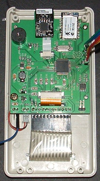
I have written the "drivers" (I guess thats the term!) for the Graphical LCD, barcode, Keyboard, RFID and Wifi. All said modules are working (though not in any way cohesively) however mechanically the LCD alignment needs moving down about 2-3mm to fit in the case window (see picture)
![]()
Mechanics (like optics in my previous project) is basically a bitch, it is the part of your project everyone see first and makes their initial decisions. In this project the challenges have been well outside my normal fields of experience but I think its a good first stab. so overall heres the lowdown of where it stands as of Rev2
The bad
- The alignment of the keypad overlay must be exact, without even the slightest error otherwise it does not lie flat and you get a really annoying keypress experience. Annoyingly some of the overlays are up to 0.5mm too wide or too narrow, the narrow ones are fine as you can live with a tiny gap, the too wide ones don't stick proper unless cut down
- The adhesive on the overlay doesn't seem to be as good as I'd hoped, some are slightly coming away. This may be down to not applying them to a clean enough surface or at the right temperature, some experimentation is required.
- The cable from the keypad overlay is too long and needs doubling up which puts pressure on the underside of it in some cases causing it to press out.
- Screw posts for attaching the PCB to the front of the case need to be about 1.5mm lower for the LCD to be flush with case and to give more headroom for the barcode scanner (it fits, just, but butts too far up against the bottom of the case and needs a little push to fit)
- (Most annoyingly) The acrylic window for the terminal is exactly 90 degrees to the barcode scanner, causing internal reflection and very degraded reading when the window is on the case, the barcode manual says it should be at an angle, I may need another re-design to get this optimal (optics again arghhh!)
- Again with the acrylic window you can see the insides and we really only want to show the barcode scanner.
- MT700 barcode takes forever to go into power down mode, also broke the connector when I pushed it too hard (see picture) so has now stopped working, the tests were good when it was working, but will need to make a new board to fix proper
- WiFi232-S does not go into power down mode, also the first module I soldered in did not work, the one I replaced it with was OK (butt ugly soldering notwithstanding) hoping for no more surprises here!
- The 8Mhz oscillator choice is bad for 115200 baud (wifi default speed) I have to use the PLL to clock it to 20Mhz or change the XTAL down to 3.5Mhz. I think I will do the latter as there is really no requirement for speed anywhere in the current system
- Programming port requires case off. For the final unit this wont be an issue as we will update over the air, but for development its a pain in the arse. Probably should have put a USB and bootloader like in the first version.
- Will probably take about 10 to 15 mins to assemble each unit.
The good
- Looks quite good (until you look at it through the acrylic window - see above)
- Not too expensive, compared to a proper injection moulded case the whole bill of materials reaches the sub- $100 price point.
- Max power consumption is around 200mA with everything on and no power management of anything so even if I did nothing I would get a days work out of a unit, from previous experience it should be possible to extend the battery life to a week or more with normal use
- During the design Microchip released a new PIC32 with double the memory (now 256K Flash/64K Ram) for just 20c more, $3.80 instead of $3.60. Not planned and not required but I certainly have no excuses now for constrained resources, I could even move to a non-serial wifi module as I could easily fit the TCP stack in if required. (Now if the bastards would only release a RN-131 for about 50% of the price I would be a very happy camper!)
- The GLCD is very readable in all conditions, much, much better than the original TFT though I have had to use a 8x16 font to achieve this and this gives me 16 chars x 8 lines of text to play with
- I have a client that definitely wants one of these terminals for each of its operators (about 40-50 units) the fact they are willing to go down this road with an untested unit/concept and absolutely no sales pressure from me is proof enough the is demand out there when the price is right. another new client has made contact and is keen but wants 13Mhz RFID not the 125Khz EM4100 I dont see any issues with that.
Of course non of this is tested real life yet, when the rubber meets the road I am expecting other challenges to appear.
In the next few days I will upload the totally unfinished firmware for the PIC32 to my github (with appropriate dodgy pre-alpha warnings) as it at least shows other how to get all the bits talking.
The future
New board Rev 3 which
- fixes the LCD window alignment
- Add MOSFETs to switch power off to WiFi and barcode modules. Both take sub-second to boot so I dont think this will be an issue
- 3.579545Mhz crystal
- Remove barcode buzzer out to mosfet (its a level not a squarewave!)
- Remove barcode decode (just use serial in to trigger good response)
- Remove WiFi reload (if you really need to do this just short the pin to gnd)
- Remove LCD ~CS (maybe), not really required as nothing else on SPI bus
- Change RFID MOD and add 2 x 10K pull-ups for barcode data/clk
- move a few IO around for better PCB design
- Move RFID to daughter board to allow change between 13.5Mhz and 125Khz formats and allow more simple/secure coil mounting
- Start writing the software - A big job, but finally something I'm quite good at :-)
The (not too) distant future
The next version on from this will need a much more professional case, I think 3D printing one would be good as I can mould it around the board a bit better and get the barcode scanner correctly positioned.
I have some contacts now for small/medium volume enclosure designs and manufacturing (Hi Emily at SZOMK and Shelly at ezpcb) a visit with a final prototype may prove fruitful
I will revisit my original designs to see what lessons can be learnt.
-
WiFi Woes
08/10/2014 at 21:32 • 1 commentPCB is back, GLCD and barcode and RFID all sweet however I think there is short under the wifi module as I cannot get a response, so I will need to try and swap the module or build another board sometime this week (groan!) - hoping its just a bad module or soldering, cant find an error on the board as when I wired in a spare module via some flying leads I got a response..
Two other little problems with the wifi module
1. The USR module refuses to go into standby low power mode at the moment, this is unfortunately a show stopper if they dont reply to me with a solution. The unit is averaging 8-10mA but when I issue the AT+MSLP=standby command to get it to sleep, the power consumption goes all over the place then back to 8-10mA within a second.
2. If the wifi is disconnected, the only way I currently can see of reconnecting is to reset it physically or via a AT+Z command,
the manual is not very good in either of these areas but a bit more experimenting should produce results. The sleep power is a bit of a show stopper if I cannot get it working :-(
Also the original RN131 module is out of stock until the end of september (groan!) but if I dont get the other module behaving I will bite the bullet and go back to it with the enevitable delay.
-
Revision 2 PCB
08/07/2014 at 05:33 • 0 commentsHi Just a quick update, the revision 2 PCB is back from seeed studios (where EasyEda make their boards) and I've assembled most of it minus a couple of components I'm still waiting for, I've managed to power it on and check the programmer can communicate (always a good start!) and will be testing it over the next few days. I've already had a re-think on the RFID and decided to put it on a daughter board to allow changing from a 125Khz to a 13.5Mhz system for another customer so there will be a rev 3 board sometime soon (hopefully before September as I'm away for 3 weeks in UK then)
-
Mechanical drawings
07/23/2014 at 23:37 • 0 commentsHave added the mechanical drawings for enclosure and keypad to file repository
-
Link to datasheets added
07/23/2014 at 08:00 • 0 commentsI have added the link to the PDF Data sheets for all the components used in the Data Collection Terminal so they're now all in one place => here
-
Wifi Module chosen
07/20/2014 at 11:16 • 0 commentsI hooked up the USR WIFI232-S serial to wifi module to my laptop and spend a while seeing how well it connected to my access point from different locations. Only 4 wires were needed +3.3V, 0V, TXD and RXD so I was able to use a small USB to TTL converter to do the testing.
While I did not do anything extensive, I managed to connect fine from up to 70M from my house which is about the same as my cell phone and a little less than the RN-131 which managed 90M.
This was the last piece I needed to check so I will add the unit to the PCB and begin laying it out later this week.
-
Power Supply
07/16/2014 at 22:47 • 0 commentsThe original design at the end of last year used a 3.7V LiPo and USB charging, this was always my preferred way and still may resurface if I do a version 2 with touch screen, however it got lost along the road to reducing the BOM and version 1 so the device is now powered from 2 x AA rechargeable batteries.
Because of this I need to boost the 2.4V to 3.3V. I originally envisaged using the RN-131 in built boost converter for this, however I've gone through the manual and asked on the forum but cannot get 3.3V out from it, the second option was an external boost converter. Plus I may want to use a different WiFi module if the tests pan out.
I have quite a few ON Semiconductor NCP1410 lying around from previous projects so I never thought anything of reusing this, however looking on the web site these look to becoming obsolete in favour of the NCP1421 which is a much better device for about the same price. ($0.76)
According to the datasheet it supplies a lot more current up to 600mA at 3.3V as opposed to 200mA for the old one, but realistically this is lower as the batteries will go down under 2V when discharging (see the eevblog episode on boost converters which is quite interesting!)
Also as the system does not have a power switch and to preserve battery life I wanted to ensure it would power off automatically after an hour or so of not being used. The NCP1410 had a shutdown but this was useless as it still discharged the battery through an internal diode, the 21 has "true power off" which means if I put it into power save mode it will disconnect the battery effectively allowing me to replace the MOSFET I currently have for the job.
I will therefore be modifying the circuit to add this in the near future and put the update in for others to comment.
Data Collection Terminal
General purpose low cost handheld terminal with screen/kbd, wifi, barcode and RFID reader for industrial or commercial (or any other) use