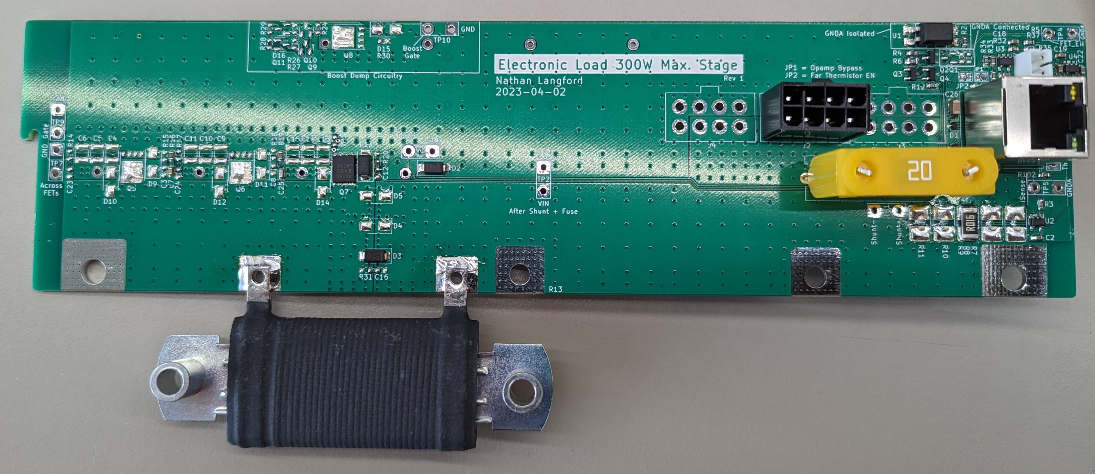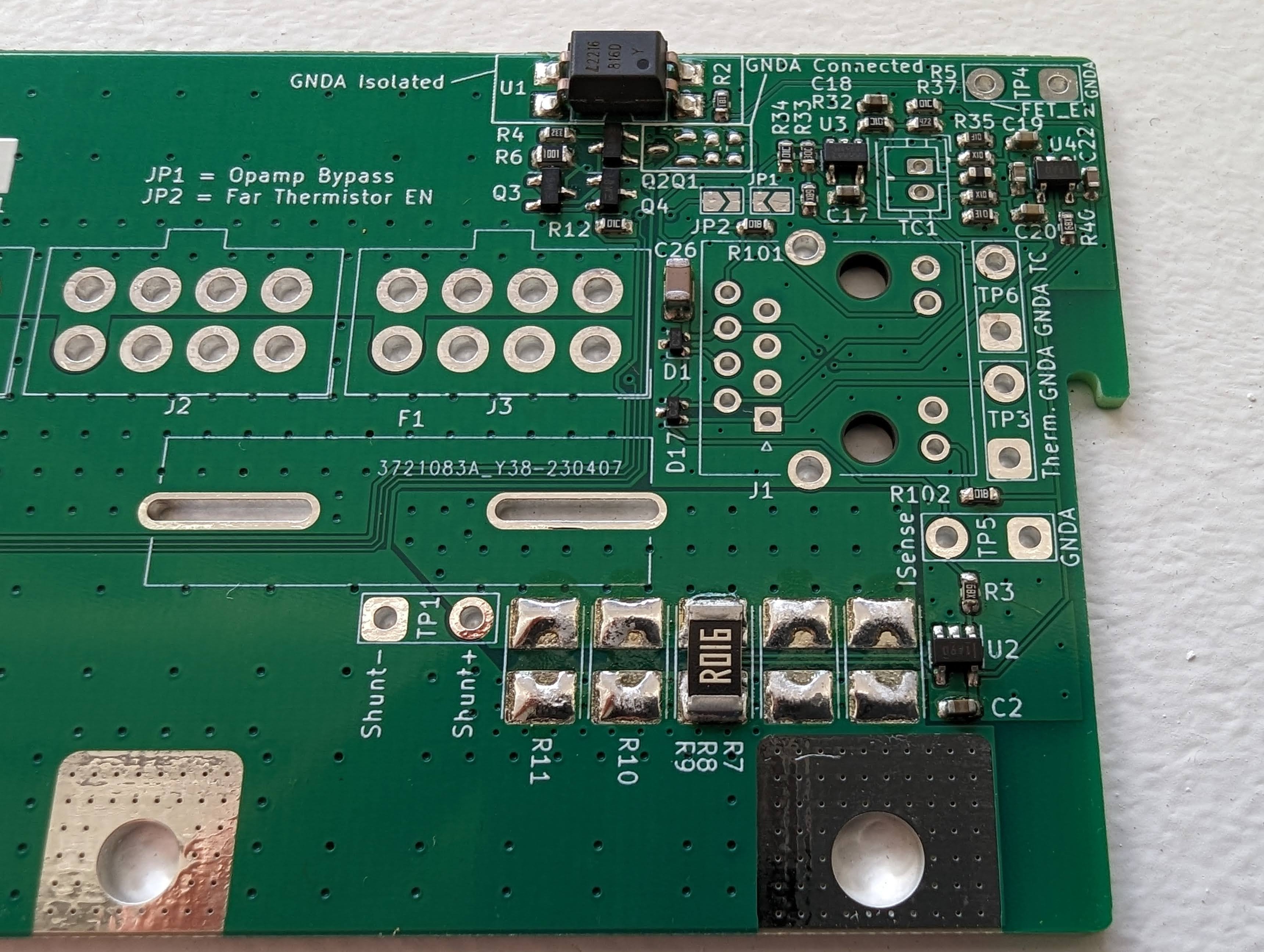
After much time was spent modifying a T962A reflow oven (Much thanks to this Hackaday.io post for guidance), it was finally time to assemble and reflow the first board. I'm starting with the 8 Ohm 19W load stage. It has the fewest components of all the variants. This is actually the first PCB I've ever done the "stencil solder paste, pick and place, then reflow" SMD assembly process on but it went well. Joints probably aren't production quality but I declare them serviceable. The load resistor, connectors, and fuse were all hand soldered after reflow.
Takeaways:
- Now that I've done the SMD assembly process myself, I think I'll lean heavily on places like JLCPCB for assembly in the future. Especially for anything more complicated than this.
- I used way too many different resistors values. I'm beginning to understand why BOM consolidation is helpful.
- Thermal reliefs for THT parts connected to copper planes really aren't optional. I'll be able to manage with the PCBs I've already had made but this will be fixed. On the large power interconnect PCB, I'll probably try to use a PCB preheater to make the job easier/possible.

Discussions
Become a Hackaday.io Member
Create an account to leave a comment. Already have an account? Log In.