 Michael Gardi
The PCBs arrived from the fab and I was anxious to check them out so I wired one up.

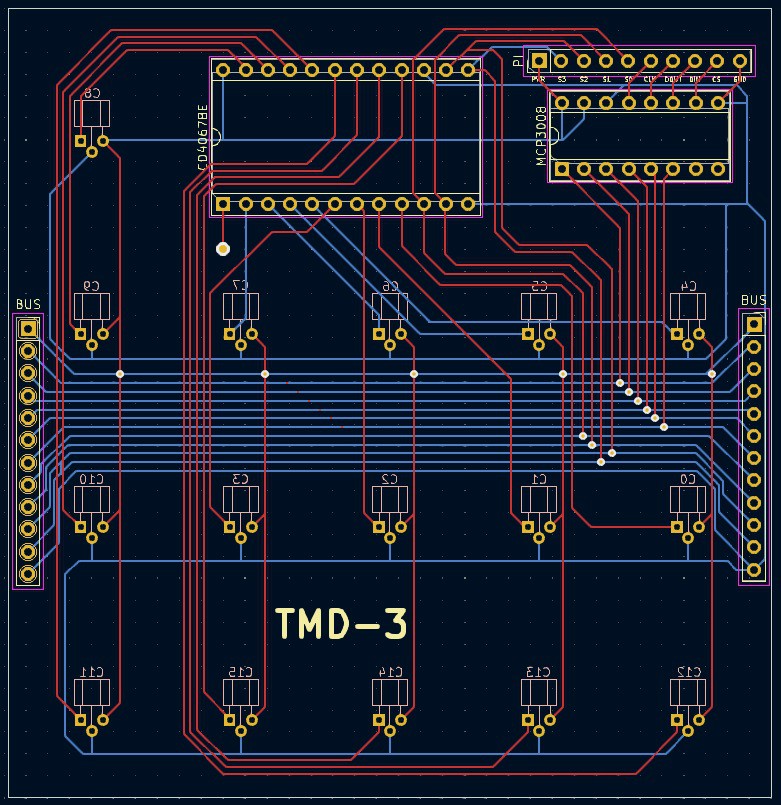
On the left is the top of the PCB with the CD4067BE multiplexer (large chip), MCP3008 8-channel A/D converter (small chip), and a 10 pin header installed. On the right you can see that I have installed a couple of the SS49E linear hall effect sensors to test with on the bottom of the PCB. Also note that the red wire is not to fix anything, it assigns the common output of the CD4067BE on this state PCB to the channel 0 (C0) pin of the MCP3008. Each of the other 5 state CD4067BEs will be similarly wired to channels 2 through 5 (C2-C5) of the MCP3008.
I wired the header on the PCB to my Raspberry Pi 4.
| State PCB Header | Raspberry Pi 4 | Description |
|---|---|---|
| PWR | 3.3V | Power |
| S3 | GPIO 18 | These 4 pins select one of 16 input channels on the CD4067BE multiplexer. |
| S2 | GPIO 17 | |
| S1 | GPIO 27 | |
| S0 | GPIO 23 | |
| CLK | SCLK | These 4 pins are used to establish an SPI connection to the MCP3008. |
| DOUT | MISO | |
| DIN | MOSI | |
| CS | GPIO 22 | |
| GND | GND | Ground |
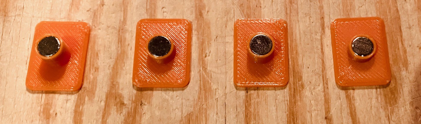
I made some test tiles that accept 6 mm x 3 mm round magnets at four different distances from the bottom of the tile (1 mm to 4 mm).
I wrote a little Python script to test the board.
import time
import busio
import digitalio
import board
import adafruit_mcp3xxx.mcp3008 as MCP
from adafruit_mcp3xxx.analog_in import AnalogIn
import pigpio

# Access the gpio pins.
GPIO = pigpio.pi()

# Select pins for the CD4067BE.
S0 = 23
S1 = 27
S2 = 17
S3 = 18

# Select pins are all OUTPUT.
GPIO.set_mode(S0, pigpio.OUTPUT)
GPIO.set_mode(S1, pigpio.OUTPUT)
GPIO.set_mode(S2, pigpio.OUTPUT)
GPIO.set_mode(S3, pigpio.OUTPUT)

# Select the C8 sensor.
GPIO.write(S0, 0)
GPIO.write(S1, 0)
GPIO.write(S2, 0)
GPIO.write(S3, 1)

# Create the spi bus to the MCP3008.
spi = busio.SPI(clock=board.SCK, MISO=board.MISO, MOSI=board.MOSI)

# Create the cs (chip select).
cs = digitalio.DigitalInOut(board.D22)

# Create the mcp object.
mcp = MCP.MCP3008(spi, cs)

# Create an analog input channel on pin 0.
chan0 = AnalogIn(mcp, MCP.P0)

# The hall effect sensor will read in the middle of the range someplace.
mid = chan0.value

while True:

    # read the analog pin
    time.sleep(0.5)
    print('Value =',chan0.value-mid)
When I first tried this script I found that the C8 sensor was not being selected. Ultimately I discovered that the S3 input on the CD4067BE multiplexer was not going high because the pin had been inadvertently tied to ground. Once fixed (by cutting the offending trace) I got good results.
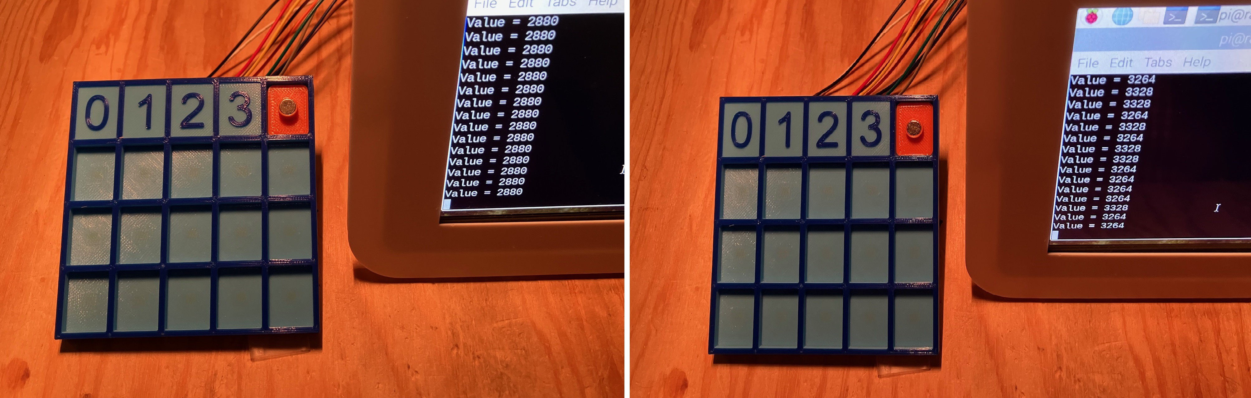
On the left a "tile" with the magnet 2 mm from the bottom, and on the right the magnet is 1 mm from the bottom. You can see that I am getting pretty good results as the Hall effect sensor readings are quite a distance apart so it should be easy to differentiate between tiles.
I'm going to make another pass at the PCBs to fix the problem I had with the S3 input. Also seeing the PCBs I realize that the pitch on the BUS connectors is way to small to easily run wires between them. I'm changing the connectors to be standard .1 inch headers.
 The updated PCB gerber files have been submitted to the fab.
Discussions
Become a Hackaday.io Member
Create an account to leave a comment. Already have an account? Log In.