 Michael Gardi
I finally got around to fully populating the state table PCB. Using the technique posted in a previous log, I carefully soldered the 16 linear hall effect sensors, then the header, multiplexor, and ADC chips to the board.
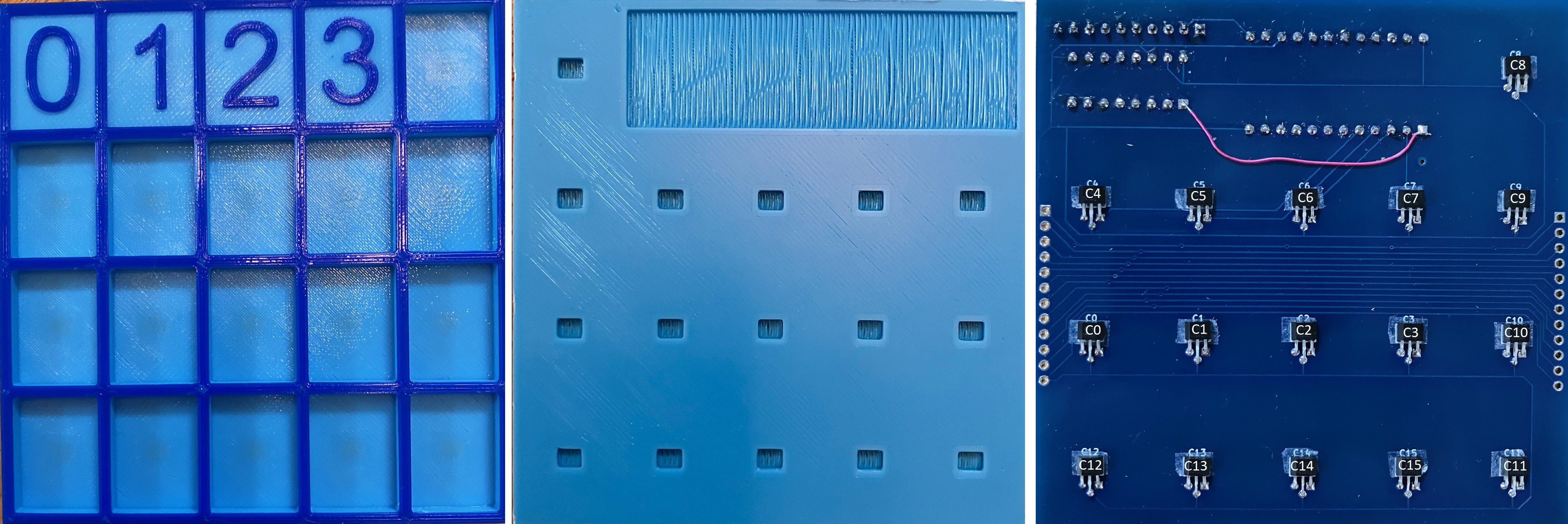
Remember that the red wire is to connect the primary input/output pin of the multiplexor to channel 0 of the ADC for this board. The other 5 boards forming the state transition table will be wired individually to channels 1-5 of this same ADC via the “bus”. I have added the sensor numbers as labels to the PCB photo for clarity. I also added the rectangular indentation to the bottom of the printed panel to accommodate the soldered pins of the ICs and header as I found that the panel would not sit flush against the PCB and sensors otherwise.
First I wanted to test the variance between sensors. I wrote a small script to measure each of the sensors in turn. Things to note:
- The script is initialized by recording the "at rest" (no magnetic field) reading for each sensor. As has been stated the sensors initially read in the middle of the range of possible values.
- If a reading varies from this initial value by more than 200, the sensor number and the value read is output.
- The emitted value is the raw reading minus the mid point value divided by 100 and rounded to the nearest integer.
import time
import busio
import digitalio
import board
import adafruit_mcp3xxx.mcp3008 as MCP
from adafruit_mcp3xxx.analog_in import AnalogIn
import pigpio

# Access the gpio pins.
GPIO = pigpio.pi()

# Select pins for the CD4067BE.
S0 = 23
S1 = 27
S2 = 17
S3 = 18

# Selct pins are all OUTPUT.
GPIO.set_mode(S0, pigpio.OUTPUT)
GPIO.set_mode(S1, pigpio.OUTPUT)
GPIO.set_mode(S2, pigpio.OUTPUT)
GPIO.set_mode(S3, pigpio.OUTPUT)

# Select the C8 pin.
GPIO.write(S0, 0)
GPIO.write(S1, 0)
GPIO.write(S2, 0)
GPIO.write(S3, 0)

# Create the spi bus.
spi = busio.SPI(clock=board.SCK, MISO=board.MISO, MOSI=board.MOSI)

# cCreate the cs (chip select).
cs = digitalio.DigitalInOut(board.D22)

# Create the mcp object.
mcp = MCP.MCP3008(spi, cs)

# Create an analog input channel on pin 0.
chan0 = AnalogIn(mcp, MCP.P0)

def selectPin(pin):
    if pin & 0b00000001:
        GPIO.write(S0, 1)
    else:
        GPIO.write(S0, 0)
    if pin & 0b00000010:
        GPIO.write(S1, 1)
    else:
        GPIO.write(S1, 0)
    if pin & 0b00000100:
        GPIO.write(S2, 1)
    else:
        GPIO.write(S2, 0)
    if pin & 0b00001000:
        GPIO.write(S3, 1)
    else:
        GPIO.write(S3, 0)

# The hall effect sensor will read in the middle of the range
# someplace. Get the middle values for all 16 sensors.
mids = []
for i in range(0,16):
    selectPin(i)
    time.sleep(0.01)
    mids.append(chan0.value)
print(mids)

while True:

    for i in range(0,16):
        selectPin(i)
        time.sleep(0.01)
        val = chan0.value-mids[i]
        if abs(val) > 200:
            print("C",i,"=",round(val/100))
    time.sleep(0.5)
For each magnet distance from 1 mm to 4 mm I recorded the values from all 16 sensors. The same magnet was used for all readings.
| C0 | C1 | C2 | C3 | C4 | C5 | C6 | C7 | C8 | C9 | C10 | C11 | C12 | C13 | C14 | C15 | |
|---|---|---|---|---|---|---|---|---|---|---|---|---|---|---|---|---|
| 1 mm | 52 | 49 | 47 | 49 | 52 | 49 | 48 | 50 | 56 | 52 | 50 | 53 | 58 | 51 | 49 | 51 |
| 2 mm | 31 | 29 | 29 | 29 | 31 | 29 | 29 | 30 | 33 | 31 | 30 | 31 | 33 | 30 | 29 | 31 |
| 3 mm | 22 | 21 | 20 | 20 | 22 | 21 | 20 | 21 | 23 | 21 | 21 | 22 | 24 | 21 | 20 | 22 |
| 4 mm | 14 | 13 | 13 | 13 | 14 | 13 | 13 | 14 | 15 | 14 | 13 | 14 | 15 | 13 | 13 | 14 |
I was pretty happy with the results. For each distance the values grouped fairly well although I would note that the difference between the lowest and highest values read was worst for the 1 mm values (11) but got better as the distance increased, 2 mm difference (4), 3 mm difference (4), and 4 mm difference (2).
In a second set of tests, for each distance, I measured the values returned from 10 different magnets. In all cases the C0 sensor was used.
| M1 | M2 | M3 | M4 | M5 | M6 | M7 | M8 | M9 | M10 | |
|---|---|---|---|---|---|---|---|---|---|---|
| 1 mm | 35 | 49 | 52 | 51 | 53 | 52 | 51 | 51 | 51 | 49 |
| 2 mm | 22 | 31 | 33 | 32 | 31 | 32 | 31 | 31 | 31 | 30 |
| 3 mm | 15 | 15 | 22 | 19 | 22 | 22 | 22 | 22 | 22 | 21 |
| 4 mm | 10 | 13 | 14 | 13 | 13 | 13 | 13 | 13 | 13 | 10 |
Again fairly good grouping although I have highlighted a number of cases where the value for a particular magnet diverged quite a bit from the "norm". The magnets that I am using are cheap and suspect not even neodymium. To try and mitigate these divergences, I have ordered some better neodymium magnets from a reputable dealer.
Although it will be a pain in the butt, I suspect given these findings that for the best results I may have to calibrate each sensor against the all tiles that will be placed at that position. We'll see. The good news it that I should only have to do this once.
Discussions
Become a Hackaday.io Member
Create an account to leave a comment. Already have an account? Log In.