 WJCarpenter
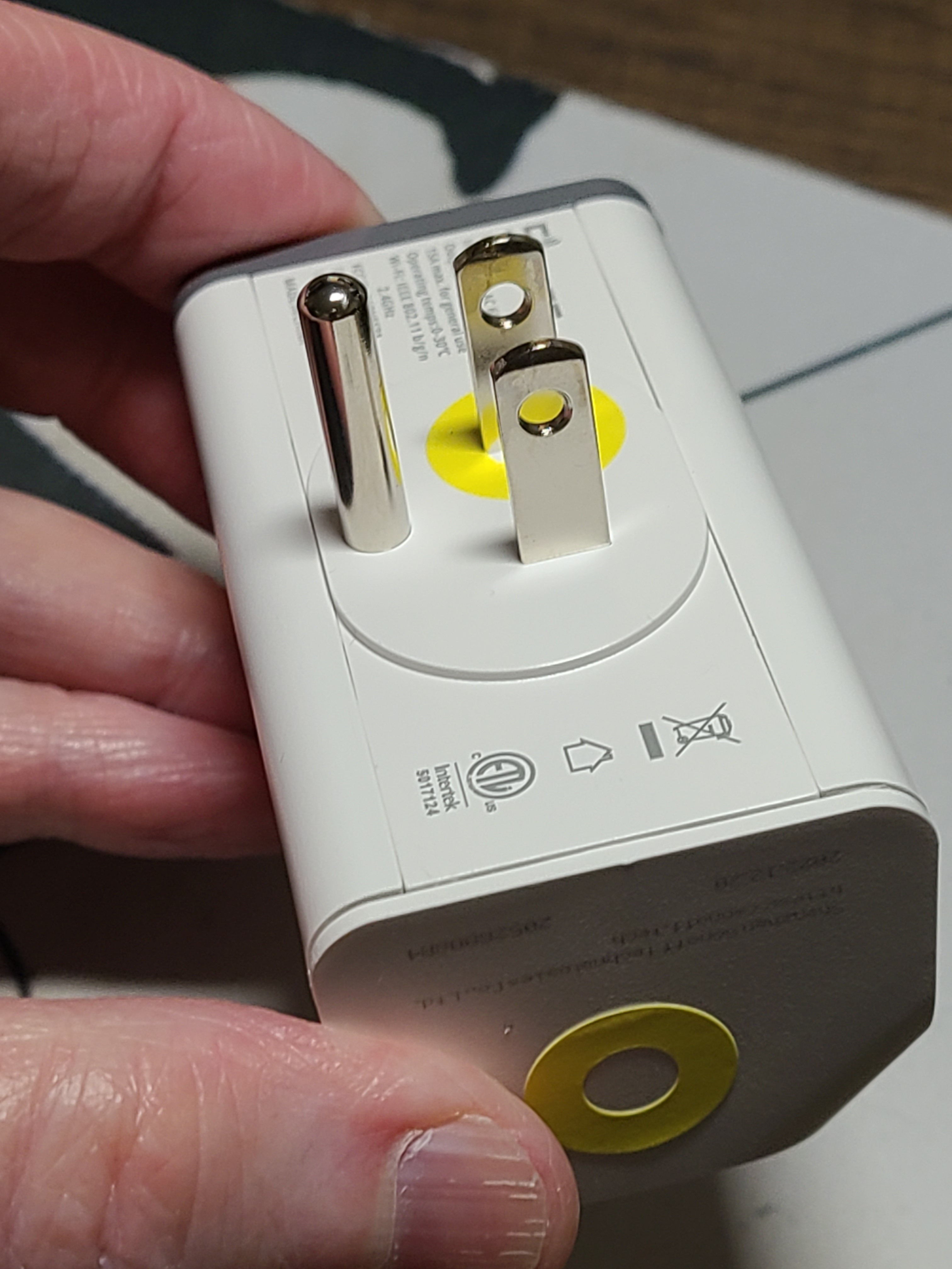
I marked all of my S31 devices with different colors so I could keep track of what was what. I have green, pink, yellow, and orange markings. Here's the yellow one:
I then set about making some initial changes to the ESPHome sample configuration. This will probably evolve a little bit over time. There are already some changes I'm planning to make.
I used a common configuration file that gets included into a configuration file specific to each separate device. For example, here is the one for the yellow S31:
substitutions:
  name: s31yellow
  alias: Yellow
  alias_icon: mdi:cloud-question
  power_on_boot: 'true'
<<: !include { file: s31.yaml.inc}
The idea of the substitution variables is to control configuration of things in the common file, which is here:
# This is a mild adaptation of the ESPHome configuration for Sonoff S31
# smart plug described here: https://www.esphome-devices.com/devices/Sonoff-S31/

# Pin     Function
# GPIO0   Push Button (HIGH = off, LOW = on)
# GPIO12  Relay and its status LED
# GPIO13  Green LED (HIGH = off, LOW = on)
# GPIO1   RX pin (for external sensors)
# GPIO3   TX pin (for external sensors)

# This file is intended to be included from another file that defines
# some configuration choices via substitution variables:
#   name:          the name of this device, appears various places
#   alias:         a functional alias, reported as a text sensor
#   alias_icon:    front-end icon for the alias sensor
#   power_on_boot: boolean, whether to turn on the relay at boot time

esphome:
  name: ${name}
  platform: ESP8266
  board: esp01_1m
  on_boot:
    then:
      - text_sensor.template.publish:
          id: i_alias
          state: ${alias}
      - if:
          condition:
            lambda: 'return ${power_on_boot};'
          then:
            - switch.turn_on: relay
      # give time for all the status goop to stop fiddling with the LED
      - delay: 60s
      - light.turn_off: i_status_led

wifi:
  ssid: !secret wifi_ssid
  password: !secret wifi_password

logger:
  baud_rate: 0 # (UART logging interferes with cse7766)
api:
ota:

# The value never changes except on a firmware update,
# so the update interval is never, and the value is
# published at boot time.
text_sensor:
  - platform: template
    name: "${name} alias"
    id: i_alias
    icon: ${alias_icon}
    update_interval: never

uart:
  rx_pin: RX
  baud_rate: 4800

binary_sensor:
  - platform: gpio
    pin:
      number: GPIO0
      mode: INPUT_PULLUP
      inverted: True
    name: "${name} Button"
    on_press:
      - switch.toggle: relay
  - platform: status
    name: "${name} Status"

sensor:
  - platform: wifi_signal
    name: "${name} WiFi Signal"
    update_interval: 120s
  - platform: cse7766
    update_interval: 30s
    current:
      name: "${name} Current"
      accuracy_decimals: 1
    voltage:
      name: "${name} Voltage"
      accuracy_decimals: 1
    power:
      name: "${name} Power"
      accuracy_decimals: 1
    energy:
      name: "${name} Energy"
      accuracy_decimals: 1

switch:
  - platform: gpio
    name: "${name} Relay"
    pin: GPIO12
    id: relay

# I changed this from a status_led component to a ligth component
# so that I could control it independently of the boring status.
# "inverted" so that it's normall off.
light:
  - platform: status_led
    id: i_status_led
    name: "${name} Status LED"
    pin:
      number: GPIO13
      inverted: true
Most of this is just taken from the sample. The two most important changes are:
- I wanted to be able to control whether the outlet was switched on at boot time. For the laundry machines, the answer is yes. For some other scenarios, the answer could be no.
- I wanted to be able to use the status LED for my own nefarious purposes (which I have not yet decided). I made sure it was turned off at boot time.
Another minor change was to expose the "energy" sensor, which was not present in the sample for whatever reason.
Discussions
Become a Hackaday.io Member
Create an account to leave a comment. Already have an account? Log In.