 J Gleyzes
Old PCB
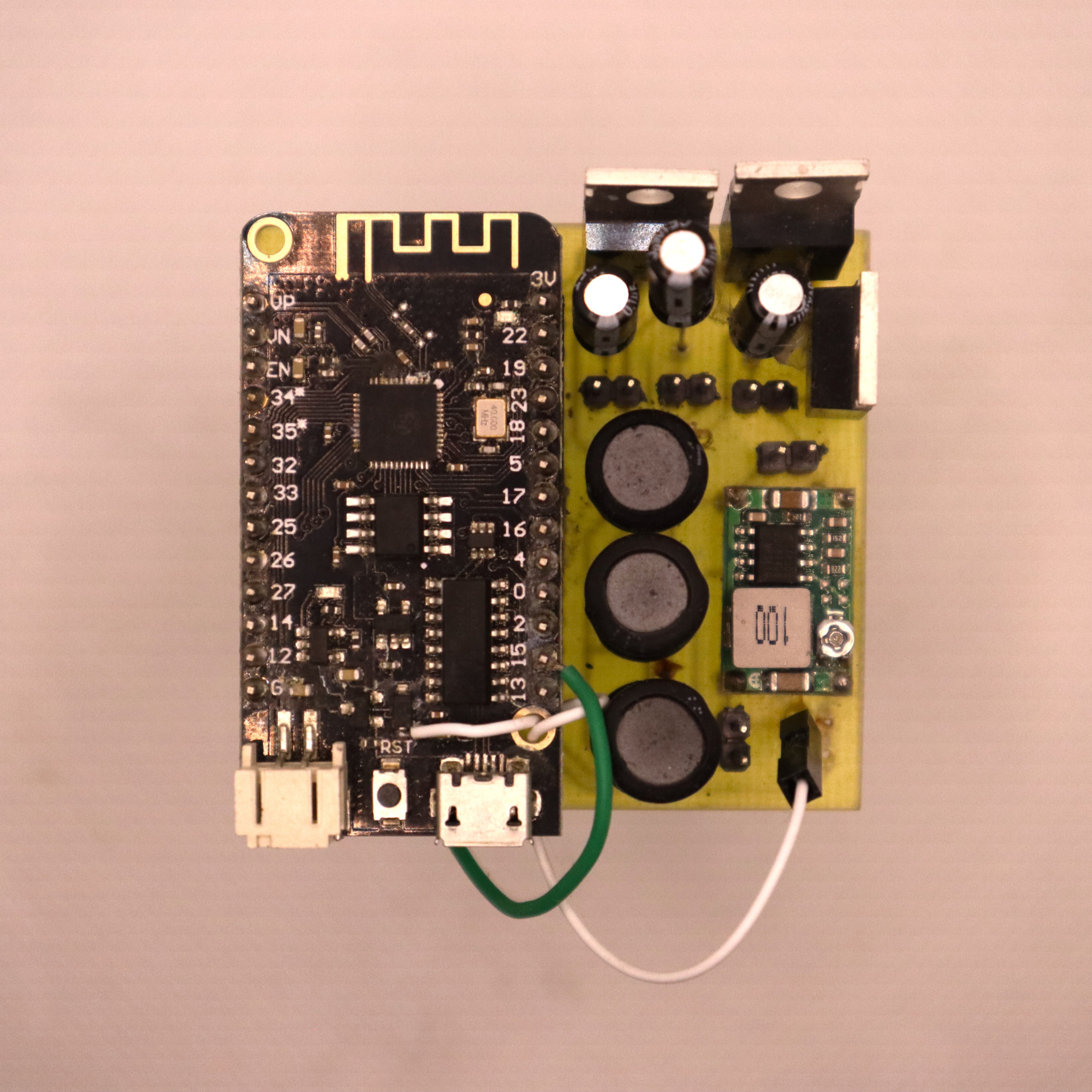
The first PCB had many problems:
- The IRFZ44N MOSFETs are not suitable for the AC current of the capacitor and coil. See this log.
- The coil can be optimized
- The capacitors are polarized. The risk is that they explode...
As a reminder, the ESP32 code alternates the operations of the disks to allow MOSFETs cooling.
This first PCB was perfect for testing but needed to be improved.
New PCB
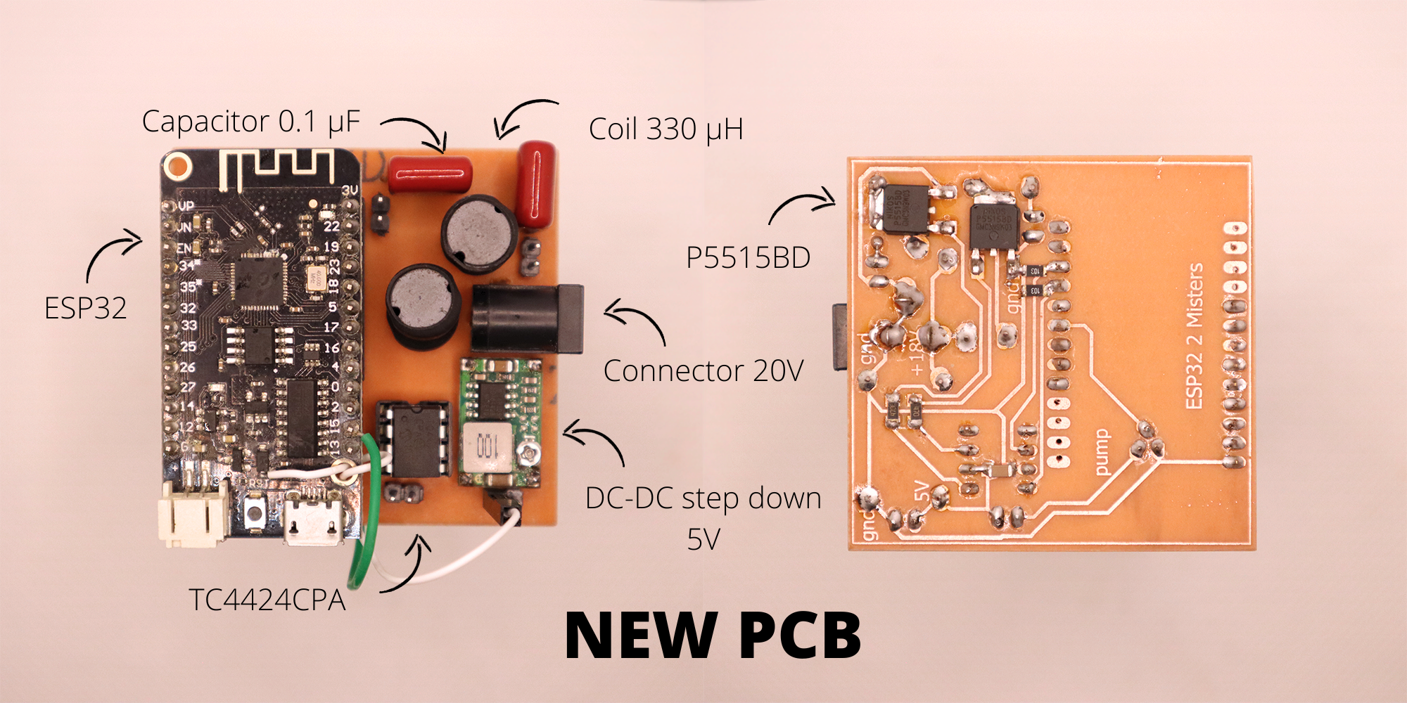
The new PCB uses only 2 disks for redundancy, the third disk is removed as the new P5515BD MOSFETs no longer heat up and can theoretically run continuously.
The addition of the TC4424CPA MOSFET driver is necessary as the ESP32 fails to activate the MOSFETs with 3.3V.
The use of a 330 µH coil and a 0.1µF capacitor allows to reach peaks at 77V allowing a good activation of the disks. The capacitor is a CBB 104J 400V 0.1µF, it is far too oversized and will have to be changed on future versions of the PCB.
The PCB is a single layer one for development, I'll do a double layers version when the circuit will be fully tested on a long term basis. I'll start these tests with the new tower on Monday.
The gerber files can be found here : gerber_PCB_V2
Here is a video of the 2 misters new PCB in operation:
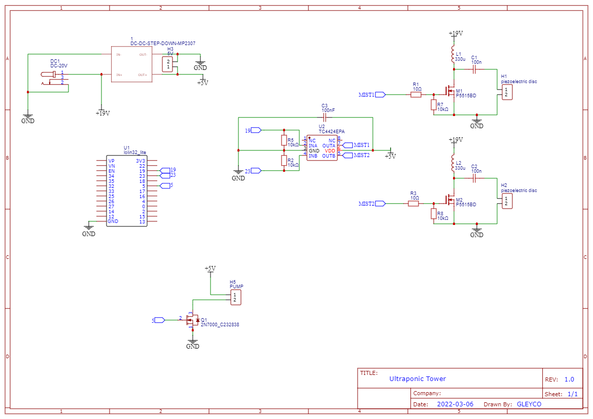
Schematics
Discussions
Become a Hackaday.io Member
Create an account to leave a comment. Already have an account? Log In.