 Petar Crnjak
This project log will be a little bit longer and full of silly robot theories and facts that you should know if using any kind of robot!
A kinematic diagram of a robotic arm is a simplified graphical representation that illustrates the arrangement of links and joints in the robotic arm. It serves to convey the essential geometric and kinematic relationships between the various components of the arm without necessarily capturing all the physical details.
In a kinematic diagram of a robotic arm:
- Links: The links represent the rigid segments or sections of the robotic arm. These could be actual physical components or conceptual representations. Links are typically depicted as straight lines connecting joints.
- Joints: The joints represent the articulation points where motion occurs. These can include revolute joints (rotational) and prismatic joints (linear). Joints are often shown as small circles or symbols, with appropriate labels indicating the type of joint and possibly its degree of freedom.
- Degrees of Freedom: The diagram may indicate the number of degrees of freedom associated with each joint, which specifies the number of independent ways that the joint can move. This information helps in understanding the arm's overall motion capabilities.
- Dimensions and Parameters: The diagram might include dimensions, angles, and lengths of the links and joint axes, which are essential for understanding the arm's geometry and for performing kinematic calculations.
- Coordinate Frames: Coordinate frames or axes are often included at each joint to show the orientation and position of each joint relative to a common reference frame. These frames help in defining the transformations between different segments of the arm.
- Motion Arrows: Motion arrows or annotations may be used to indicate the allowed range of motion or direction of movement for each joint.
A kinematic diagram provides a clear visual representation of the robotic arm's structure and kinematic relationships, making it easier to analyze and understand its behavior without delving into complex mathematical equations or detailed physical designs. It's a valuable tool for initial design, analysis, and communication among engineers, researchers, and anyone interested in robotics.
Inverse kinematics is a fundamental concept in robotics that involves determining the joint angles or parameters of a robotic mechanism in order to achieve a desired end-effector position and orientation. In simpler terms, it's the process of calculating the joint configurations that will result in a specific pose (position and orientation) of the robot's end-effector (e.g., its hand or tool).
In a robotic arm, for example, the forward kinematics process involves calculating the position and orientation of the end-effector based on the given joint angles. Inverse kinematics, on the other hand, works the opposite way: given a desired position and orientation for the end-effector, it calculates the joint angles that will achieve that particular pose.
Inverse kinematics can be quite complex, especially for robots with multiple joints and degrees of freedom. Solving inverse kinematics involves finding solutions to sets of nonlinear equations that relate the joint variables to the desired end-effector pose. Depending on the robot's geometry and the specific task at hand, there may be multiple solutions, a unique solution, or even no solution.
Inverse kinematics is crucial for tasks such as trajectory planning, motion control, and object manipulation, as it allows the robot to determine how to move its joints to achieve a specific goal in its operational environment. It's used in applications ranging from industrial robotics and automation to animation and simulation.
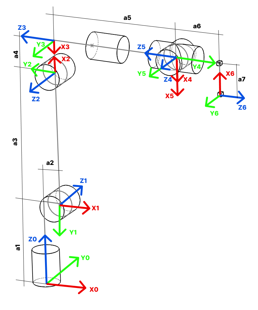
Image 1 - kinematic diagram of PAROL6 robotic arm.
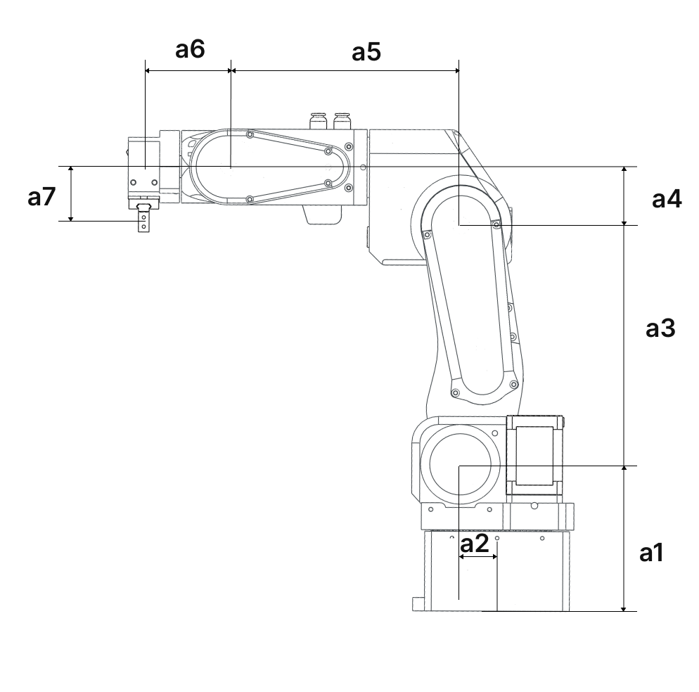
Image 2 - kinematic diagram of PAROL6 robotic arm.
Link lengths!
| a1 | 110.50 mm |
| a2 | 23.42 mm |
| a3 | 180.00 mm |
| a4 | 43.50 mm |
| a5 | 176.35 mm |
| a6 | 62.8 mm |
| a7 | 45.25 mm |
Denavit-Hartenberg parameters are a set of standardized parameters used to describe the geometry and kinematics of robotic arms and mechanisms. They provide a systematic way to represent the transformation between consecutive coordinate frames along a robot's kinematic chain. These parameters were introduced by Jacques Denavit and Richard S. Hartenberg in the 1950s and have become a fundamental tool in robotics.
The Denavit-Hartenberg parameters consist of four values associated with each joint of a robotic arm:
- Link Length (a): The distance between the common normal (perpendicular) to the current and next joint axes, measured along the previous joint axis.
- Link Twist (α): The angle between the common normal of the current and next joint axes, measured along the previous joint axis.
- Link Offset (d): The distance between the joint axes along the common normal, measured along the current joint axis.
- Joint Angle (θ): The angle of rotation or translation about the current joint axis to align the coordinate frames.
These parameters are defined for each pair of consecutive joints in the robot's kinematic chain. By applying a sequence of transformations using these parameters, you can calculate the overall transformation matrix that represents the position and orientation of each link relative to a reference frame.
The Denavit-Hartenberg parameters provide a consistent and concise way to model and analyze the kinematics of complex robotic systems, making them a widely used approach in robot design, control, and simulation.
| Joint angle | Link twist | Link offset | Link len | ||
| JOINT | LINK(n,i) | θ THETA | α ALPHA | r,a [mm] | d [mm] |
| 1 | Base | TH1 | -pi/2 | a2 | a1 |
| 2 | Shoulder | TH2 - pi/2 | pi | a3 | 0 |
| 3 | Elbow | TH3 + pi | pi/2 | -a4 | 0 |
| 4 | Wrist 1 | TH4 | -pi/2 | 0 | -a5 |
| 5 | Wrist 2 | TH5 | pi/2 | 0 | 0 |
| 6 | Wrist 3 | TH6 + pi | pi | -a7 | -a6 |
Discussions
Become a Hackaday.io Member
Create an account to leave a comment. Already have an account? Log In.