 Petar Crnjak
Design Approach
PAROL6 hardware and software design was driven in large part by Faze4 and CM6. From faze 4 mechanical design and from CM6 software and control approach. Advantage of building these robots before this one was the community and contributions to the projects from the people. People build unity simulators, ros control implementation, custom controllers, and modified STEP files... The goal is, like previous robots, to make as much open source as it can. Some of the guidelines that guided the design:
- PAROL6 was built with a specific purpose in mind; Small automation like picking PCBs and placing them in test jigs, adding thru-hole components to PCBs... Another goal was for it to be used in an education setting where one PAROL6 can be used by one student, not 10 students per 1 robot.
- It needs to have a robust simulator and GUI for easy offline programming. The ability to test your programs without a real robot is time-saving and is being done in most professional and industry-standard robots.
- Previous robots of mine used plastic gearboxes and that is a big mistake. They are way too unreliable and bend too much. PAROL6 uses precision planetary gearboxes with 10-15 arcmin backlash (harmonic gearboxes usually have around 5 arcmins). By using quality gearboxes robot has much better repeatability and precision and can make smooth trajectories,
- Robots need good connectivity to interact with the users and the world. PAROL6 has 2 isolated Inputs and 2 isolated outputs for controlling grippers, relays, pneumatics, or connection to PLC-s. It also has a CAN bus for connecting grippers or external devices. To communicate with a PC it uses USB.
- PAROL6 was built with grippers in mind and has routed pneumatic tubes and wires for grippers to its Forearm region.
- A big part of PAROL6 is its software that was again built around Tkinter as GUI and Petar Corke's Python robotic toolbox. That combination has proven to be effective in CM6 and was refined here, Because of that it has a lot of features that no other open-source robotic arm has.
- PAROL6 was designed to be easy to build by using large 3D printed parts and an intuitive design. Also, I believe many DIY robotic arm projects suffer from bad building instructions that lock out some potential users, so PAROL6 has detailed step-by-step building instructions.
WHY planetary gearboxes and belts?
The robot is designed around precision planetary gearboxes on joints that are subject to most torque. These would be joints 2 and 3. Joint one uses belts and a larger motor. For joints 4 and 5 belts are used and for 6 a smaller planetary gearbox. The design was so that motors are not on the axes that they are actuating. By doing that you remove mass to the bottom of the robot and reduce the inertia of the joints. A spherical wrist was used to make inverse kinematics calculations simpler. For the forearm and upper arm section wires and tubes run thru the robot and also from the elbow to the base are hidden. The only section where wires are visible are from the upper arm to the elbow. By hiding wires and tubes they are protected from outside elements like tangling mechanical damage and more.
Motors on most joints are not hidden. By doing that it is easy to add additional closed-loop stepper drivers to the motors and make the robot closed loop.
For the joints, 1,2,3 installation of closed-loop drivers is just straight forward as mounting then. For joints 4,5 and 6 minor robot redesign will need to be made for esthetic parts. Only the forearm will need to be extended by 3 cm to allow for PCB to mount on Joint 6.
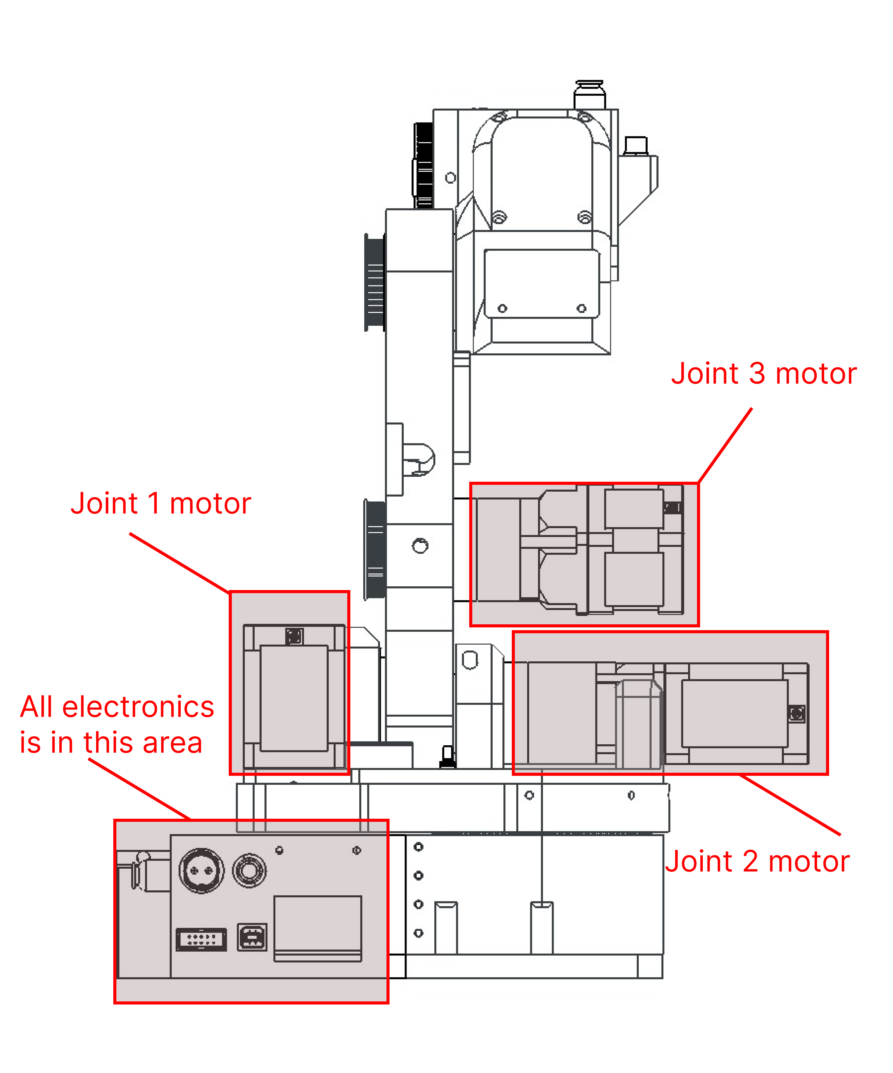
MOTOR LOCATIONS

WIRING
Wiring is done similarly to the Faze4 robot except only visible wires are from the upper arm to the elbow. The two images below show how the wiring is done for the robot. Blue are pneumatic tubes while green are wires.


BELTS AND TENSION
Belt tension is done with small ball bearings. The usual diameter of the bearing is 8mm if you see that that tension is not enough you can use a 10mm bearing. Bearings can be mounted on both sides of the belts. Joint 1 also uses a belt but it is hidden so taking pictures of it is really hard.


Discussions
Become a Hackaday.io Member
Create an account to leave a comment. Already have an account? Log In.