 Petar Crnjak
To test PAROL6 control board connection to your robot you can use stock software or use testing software. Testing software is more safe and interactive for users. It can be found at github. Once you flash your PAROL6 control board testing will start.
Stepper drivers test
The code will try to communicate with stepper drivers. Output1 and Output will go from high to low every 1s and LED1 and LED2 will flasg. If everything is okay you will get output like this on serial:
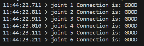
If the stepper driver is faulty or not connected you will get:

If stepper drivers are good your stepper motors should spin at a low speed using moderate current of 200-300 mA.
Flash memory test
In the serial terminal write # FLASH and press enter. You should get an output like this for a successful test.

LIMIT test
In serial terminal write # LIMIT and press enter. You should get a output like this if you activate the switch.

IO
In serial terminal write # IO and press enter. You should get an output like this:
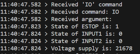
If you change the state of ESTOP, INPUT1 or INPUT2 you will see states changing. You will also be able to see the voltage of your power supply in mV!
Discussions
Become a Hackaday.io Member
Create an account to leave a comment. Already have an account? Log In.