In recent posts I've said that I wasn't happy with the mcu and surface-mount stuff being visible on the module's pcb alongside the through-hole stuff. I loved the way the feather looked when reversed but it doesn't have enough GPIO exposed.
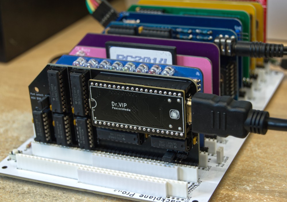
So I designed my own RP2040 board to meet my needs for this project. I'd like to introduce Dr.VIP (an anagram of RP DVI). I've split that off into its own project because it'll have a life of its own and be useful for other projects.
In short it's an RP2040 board with:
- HDMI (sorry, DVI) socket
- all GPIO exposed (other than the 8 used for DVI), that's 22 free GPIO
- DIP styling, with the SMD components on the underside
- you can mount it the other way up like a regular dev board if you like (obviously reverses the pinout)
- It's not green!
I'll definitely be offering this separately.
The second important update relates to the module itself, which is now updated with more logic so that:
- it can now read from and write to both ports, thus adding the 'VRAM read' feature and completing the TMS functionality (at least hardware-wise)
- it can now be set to use ports $98/99 or 08/09, meaning that it can be used with cp/m machines or classic RC2014 machines using the ACIA serial chip (which clashes with the MSX ports)
Separating the RP2040 from the module also has the advantage that if I want to prototype any small updates to the main module, it's now just a simple through-hole board with no assembly of small parts. If there is a hardware update, users will be able to update just the through-hole pcb or just the Dr.VIP, not necessarily everything.
I've tried to make the jumpers as user-friendly as possible:
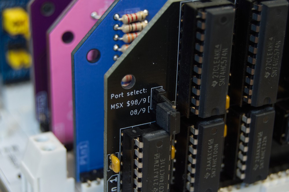
What does the part about the ports mean? Well, this:
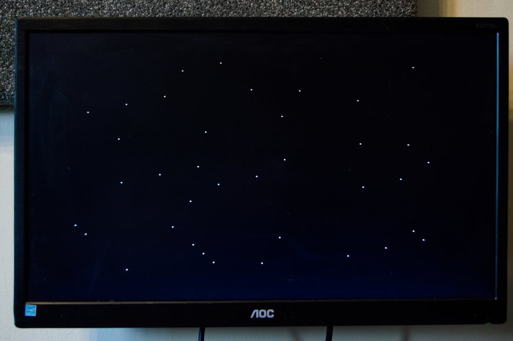
I know what you're thinking: "a starfield, whoop-de-do..."
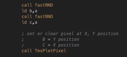
However, this does represent an important step forward. The previous version of the board couldn't have displayed this program properly.
The little program above uses TmsPlotPixel from J B Langston's excellent library. It (and any routine that wants to plot or draw to a bitmap screen) depends on being able to read the TMS chip's VRAM.
You can get around this in software by keeping your own buffer. This would be at the expense of some speed and about 6k of ram (and more if you want to read the colour value). None of the existing examples for the RC2014 TMS video module make use of the plot routine so this didn't seem like a priority to me.
However, I came up against it and realised that it would be a necessary feature for this project.

So despite adding a bunch of logic, having to add to my software and designing the Dr.VIP board (which is a lot of changes all at once) this new version seems to be working like a charm. I'm still testing but to my surprise, I feel that this is just about finished.
What can you use this video module for?
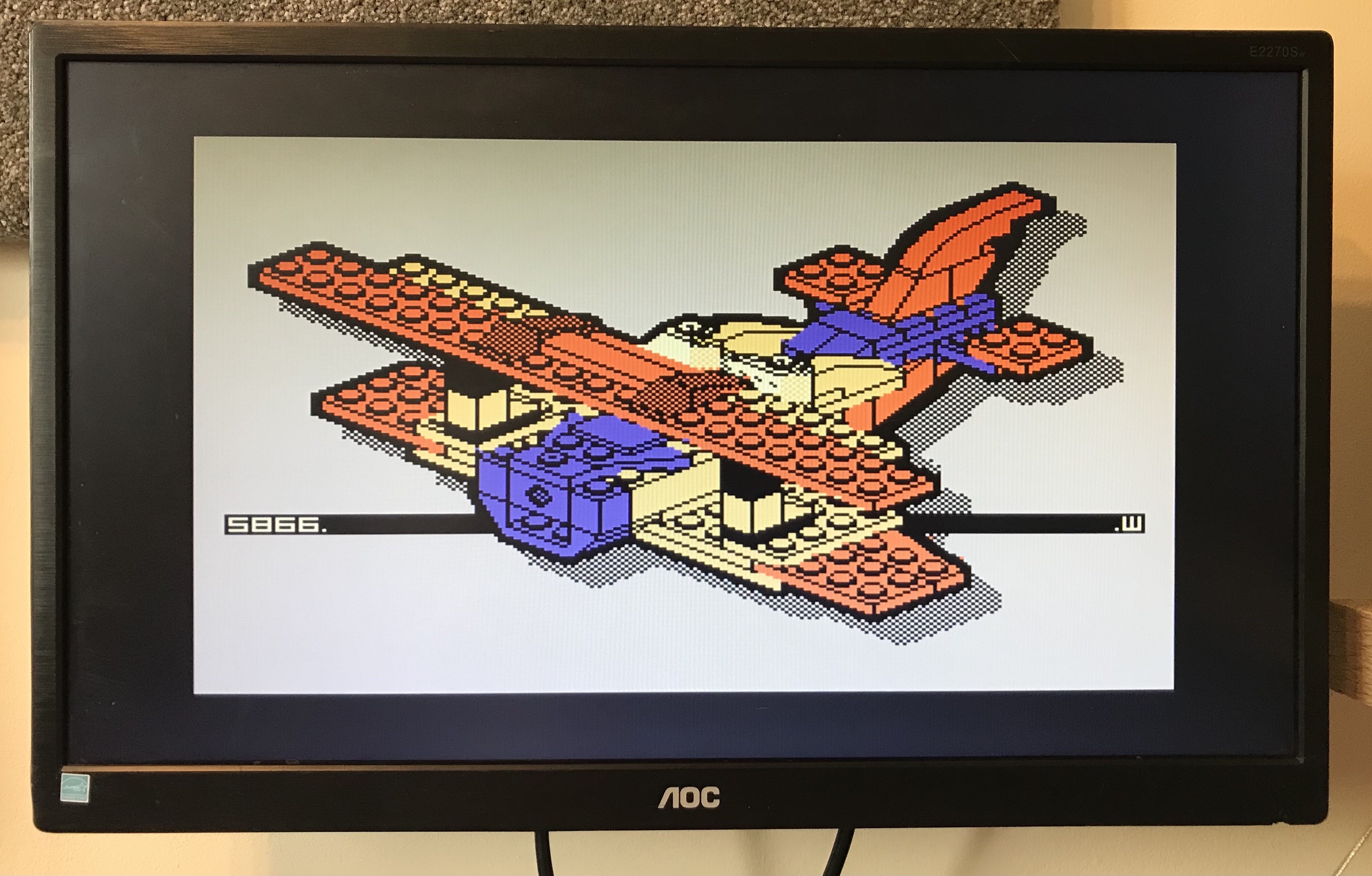
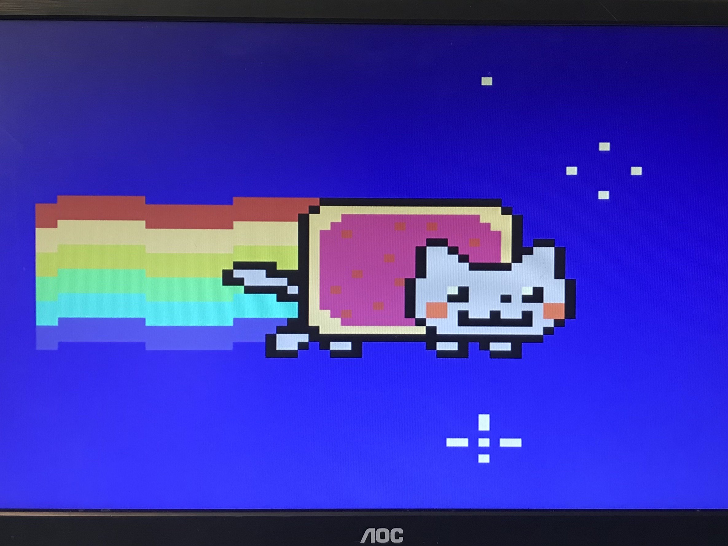
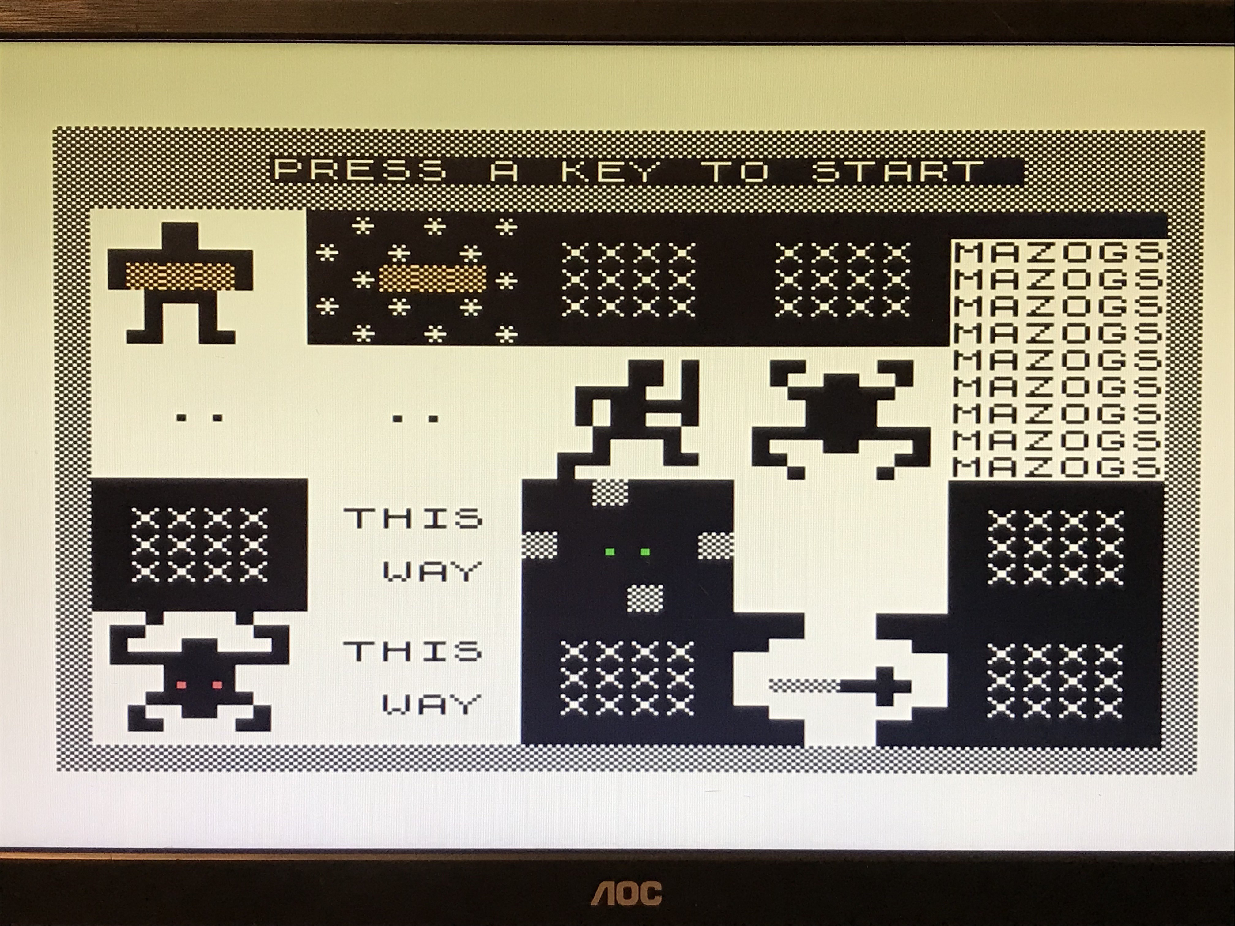
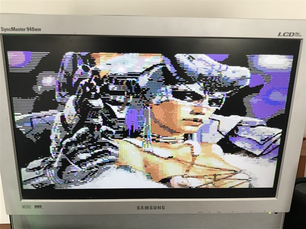
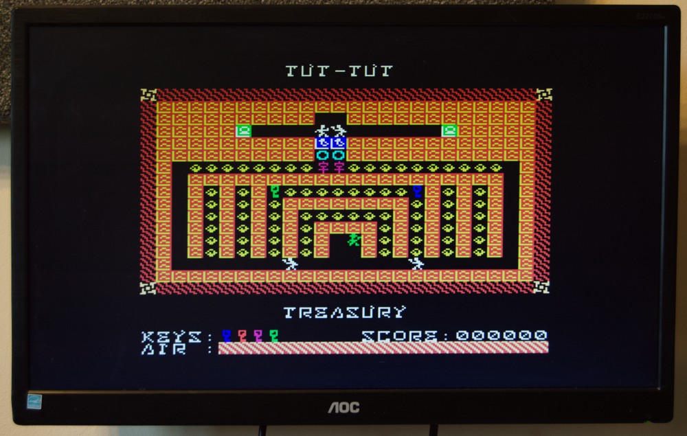
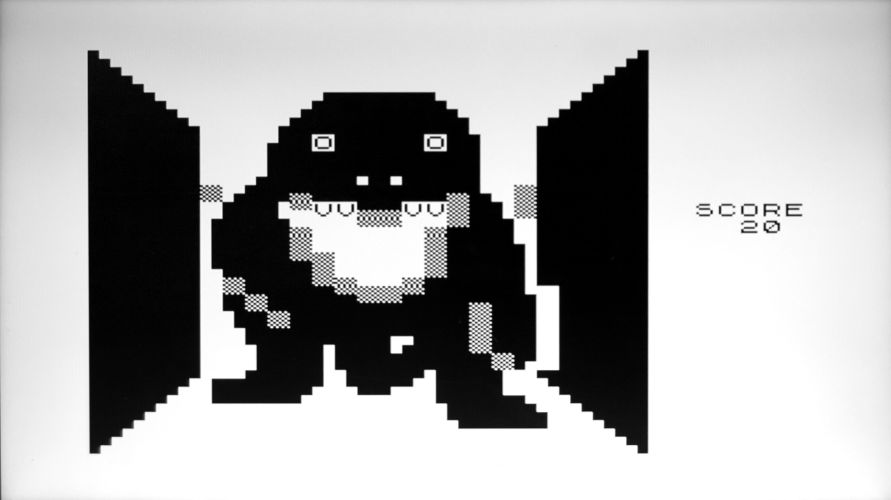
J B Langston's TMS9918A module has been around for a long time. I've gathered together the examples that I've found (and built them for cpm and classic machines). These include demos and 'screen2' and 'screen3' artwork. I've added to that collection my own ports of 3D Monster Maze and Mazogs and (breaking news) I've been working on a port for RC2014 and hopefully MSX of David Stephenson's excellent game Tut Tut. (All shown below looking nice and clear and vibrant using my video module.) The module is also connected to the serial lines, so from startup it can display the OS stuff using the TMS 40-col text mode, and potentially accept keyboard input too.
Discussions
Become a Hackaday.io Member
Create an account to leave a comment. Already have an account? Log In.