 Sebastian
In previous posts we already discussed different topology options for the decade resistor. Let's refresh our memory with an excerpt of the actual schematic showing the topology chosen for this project:
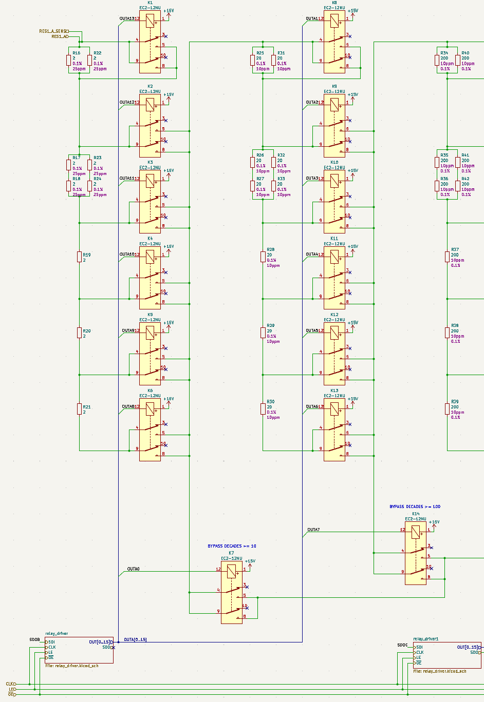
In contrast to previous schematics I included relays instead of simple switch symbols in order to look at different aspects of switching - in particular the effect of the contact resistance of the relays, which impacts the performance of the decade resistor, not only, but especially when a decade is shorted.
Bypassing upper decades
In order to improve the accuracy of the programmable decade resistor at low resistance values, additional switches can be introduced. These switches would bypass all higher decades that otherwise would be in series (although shorted), and therefore reduce the error caused by contact resistance. For the intended application it's probably not justified to add such bypass switches after decades having too large of a resistance value, like 10 kΩ and up, because then
- the rather low contact resistance of the relays (typically well below 100 mΩ) is below the tolerance of the resistors and
- the number of contacts bypassed decreases further and further, deminishing the returns.
With these considerations I decided to use such bypasses after each of the three lower decades only, increasing the total number of relays by three. Two of those relays (K7, K14) can be found in the excerpt of the schematics (see above).
Shorting a decade
When shorting the first decade (i. e. selecting 0 Ω) the simplest approach would be to just close relays K1, K2 and K7 (bypass). However, the resistance could be reduced by paralleling one or more taps of the resistor network. But how large would the effect be? And is it really worth it? Short answer: No. Long answer below.
I did the math assuming a contact resistance of 40 mΩ (both relay poles in parallel). The values take into account the resistance values of resistors connected in parallel with a closed switch, resulting in these odd values shown below:
| Relays closed | Resistance (Ω) | Absolute difference (Ω) | Relative difference (ppm) |
|---|---|---|---|
| K1, K2, K7 | 0.1184615385 | <baseline> | <baseline> |
| K1, K2, K3, K7 | 0.1176923077 | -0.0007692308 | -6493.506 |
| K1, K2, K3, K4, K7 | 0.1176920230 | -0.0007695154 | -6495.909 |
| K1, K2, K3, K4, K5, K7 | 0.1176920230 | -0.0007695155 | -6495.910 |
| K1, K2, K3, K4, K5, K6, K7 | 0.1176920230 | -0.0007695155 | -6495.910 |
Closing relay K3 can reduce the resistance by 0.65%. This sounds like something, but it's not even a milli-ohm in absolute terms. Since the contact resistance of relays changes over time (and probably switch current etc.) the difference is absolutely irrelevant. Closing even more relays makes even less sense (due to the series resistance in the additional relay’s signal path). For the higher decades improvements would be only about 1/10, 1/100, 1/1,000, 1/10,000 and 1/100,000 of the values shown above.
On the other hand, closing additional relays causes more switching cycles and increases power dissipation that might support a temperature drift of the resistors (if non-latching relays are used).
And that's why I did not implement such a software "feature".
Next steps
We have a general idea of how to control the relays in order to achieve a certain nominal resistance value using the selected topology. We know the effect of the relays' contact resistances on shorted decades. But what is the actual resistance that is selected - be it a short or any other value? How can we make sure that the actual resistance is as close to the nominal resistance as possible? That's what we have to look into in the next log entries.
Discussions
Become a Hackaday.io Member
Create an account to leave a comment. Already have an account? Log In.