In the last post we worked on some implementation details to consolidate the bill of material while improving the power rating of the decade resistor. However, we didn’t fully analyze the design regarding power dissipation.

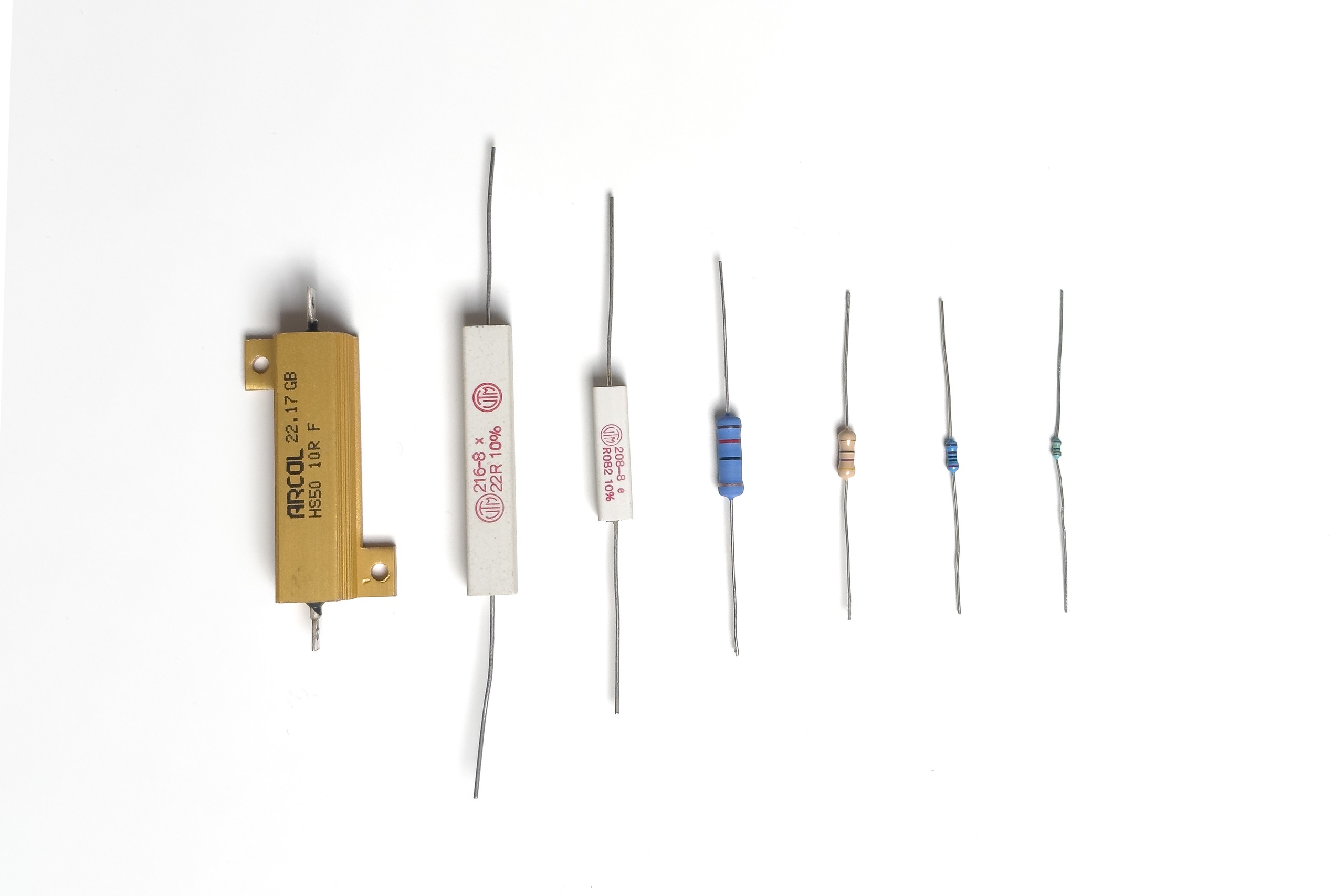
A bunch of (power/leaded) resistors with different power ratings
So let’s do that now and get some definitions out of the way:
| n | Decade n providing resistance values 0 Ω, 1⋅10n Ω to 2⋅10n Ω |
| Rn | Total resistance of decade n as set by the switches |
| R0n | Resistance of an individual resistor of decade n (in the example: R0n = 2 Ω) |
| P0n | Power rating of any individual resistor of decade n @ power rating |
| Imax,n | Maximum allowable current for decade n |
| Pmax,n | Maximum allowable power dissipation for decade n |
| Umax,n | Maximum allowable voltage for decade n |
| Imax,tot | Maximum allowable current for the programmable resistor (all decades) |
| Pmax,tot | Maximum allowable power dissipation for the programmable resistor (all decades) |
| Umax,tot | Maximum allowable voltage for the programmable resistor (all decades) |
Note: I don't think that hackaday supports inline LaTeX. Please let me know if it does.
The definitions imply that we use identical resistors throughout a decade. For this post we also assume that the power rating of all resistors are the same. In reality this is not the case. That’s one of the reasons for part 2 of this post…
Exemplary calculation for the first decade

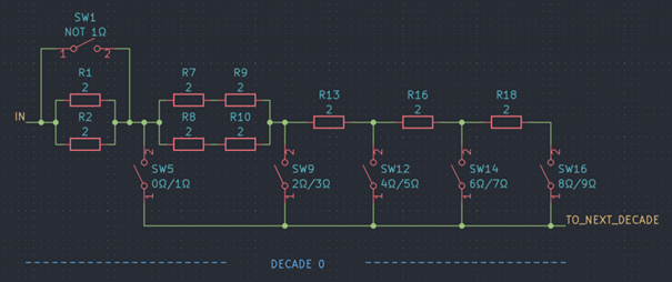
Let Imax,0 flow into the first decade (n = 0, R00 = 2 Ω) with all switches open except for SW12. The resulting resistance is R0 = 5 Ω = 2.5 R00. Then:
- a current of 0.5 Imax,0 will flow through the resistors with the designators R1, R2, R7, R8, R9, R10 (see schematic above)
- a current of Imax,0 will flow through the resistor with the reference R13
Hence Imax,0 is defined by the current that flows through R13 when the dissipated power equals its power rating:
The maximum total power dissipation of the decade is the sum of the power dissipation of the individual resistors (at their respective current). Accordingly:
The maximum allowable voltage is:
Table for decade n
To generalize the example shown above, here's a table showing the results for all resistance values in tabular form.
| R0 / R0n | Imax,n | Pmax,n | Umax,n |
| 0 | limited by relays | limited by relays | limited by relays |
| 1 | 2 I0n | 2 P0n | sqrt(P0n ⋅ R0n) |
| 2 | 2 I0n | 4 P0n | 2 sqrt(P0n ⋅ R0n) |
| 3 | 2 I0n | 6 P0n | 3 sqrt(P0n ⋅ R0n) |
| 4 | I0n | 2 P0n | 2 sqrt(P0n ⋅ R0n) |
| 5 | I0n | 2.5 P0n | 2.5 sqrt(P0n ⋅ R0n) |
| 6 | I0n | 3 P0n | 3 sqrt(P0n ⋅ R0n) |
| 7 | I0n | 3.5 P0n | 3.5 sqrt(P0n ⋅ R0n) |
| 8 | I0n | 4 P0n | 4 sqrt(P0n ⋅ R0n) |
| 9 | I0n | 4.5 P0n | 4.5 sqrt(P0n ⋅ R0n) |
Considerations for multi-decade resistors
If the power rating of the individual resistors in the programmable resistor are identical, the maximum current Imax,tot is limited by the decade with the highest resistance. To prove this, we show that the largest maximum permissible current of a higher decade m is still less than the smallest maximum permissible current of a lower decade n < m.
1. Determine the smallest maximum permissible current for the lower decade n
With the total resistance of a decade of Rn = ln ⋅ R0n, the smallest maximum current for decade n results for ln > 3 (see table for sigle decade). Therefore:
2. Determine the largest maximum permissible current for the higher decade m
With the total resistance of a decade of Rm = lm ⋅ R0m, the largest maximum current for decade m results for lm in {1, 2, 3} (see table for sigle decade). Therefore:
3. Utilize the assumptions
If m is the next-higher decade (i. e. m = n + 1), the resistor value for decade m is ten times larger than for decade n
Also, we assumed that the power ratings of all resistors all equal:
4. Bringing it all together
Conclusion and next steps
The main take-aways are:
- The maximum power rating of a decade can vary depending on the selected resistance value. Therefore it makes sense to calculate and display the applicable power rating for the resistance value set by the user instead of having a fixed rating for all resistance settings
- Using the topology and applying the aforementioned assumptions (in particular: same power rating for all resistors), the power rating is at least two times the power rating of the individual resistors
- Then the power rating of the programmable resistor is limited by the highest non-zero decade
The next post in this series will focus on the actual component selection and the implications on the subject of the power rating of the programmable decade resistor.
 Sebastian
Discussions
Become a Hackaday.io Member
Create an account to leave a comment. Already have an account? Log In.