Log backlog got big again...
I've been plugging away at making little CNC machines and writing about it. And making little things, few of which have much use apart from tinkering with the thing-making machine. Earlier ̶t̶h̶i̶s̶ last year I randomly discovered that there are several scale modeling clubs around here, including the Midwest Model Shipwrights. Might people who actually make little things have some interest in actually using a little CNC to make actual little things for the thing they do?
Now, these Model Shipwrights are very good at making the things that they already make. And they already make all the things that they need to make model ships. And they know a lot about making model ships. Viz:
| org | forum | journal |
| Nautical Research Guild | Model Ship World | Nautical Research Journal ISSN 0738-7245 |
| Ships of Scale | Ships of Scale | The MSB Journal ISSN 1913-6943 |
There are journals. With ISSNs. Not just one.
So I'm not going to tell these people how to model ships.
...
But I ventured to show up at a meeting with some example widgets and asked if making such things seemed like an interesting capability, and what sorts of ship model things might be interesting to make differently with a different tool.
That went well enough to gain an invitation to return, some examples of things to try, and some material samples.
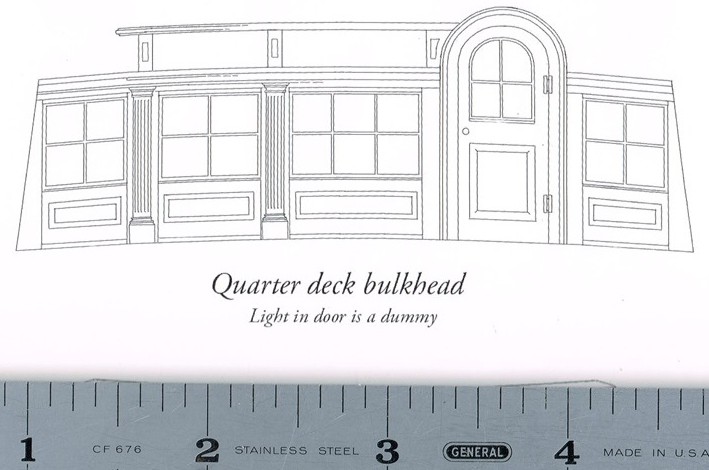
Things to try that might prove interesting included a drawing of window frames, which "usually present a challenge for modelers":
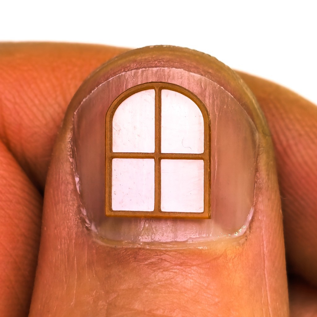
That's where the window in my thumb comes from. We'll get back to that...
This post grew long before it got to the end that I had in mind at the start. It's mostly but not entirely about little windows. If I'm saying this is doable, I probably should show at least one example of process from idea to result. That said, this is more an illustration of how some ideas evolved when the tool at hand was a little CNC mill and not so much a tutorial for CAD or CAM or steps to replicate this result.
Show > Tell: What useful work could a little CNC do for a modeler of ships?
The first example I tackled was this "trail board" -- one of the pair of decorated boards that sometimes dress up the pointy (or blunt*) end of a ship.
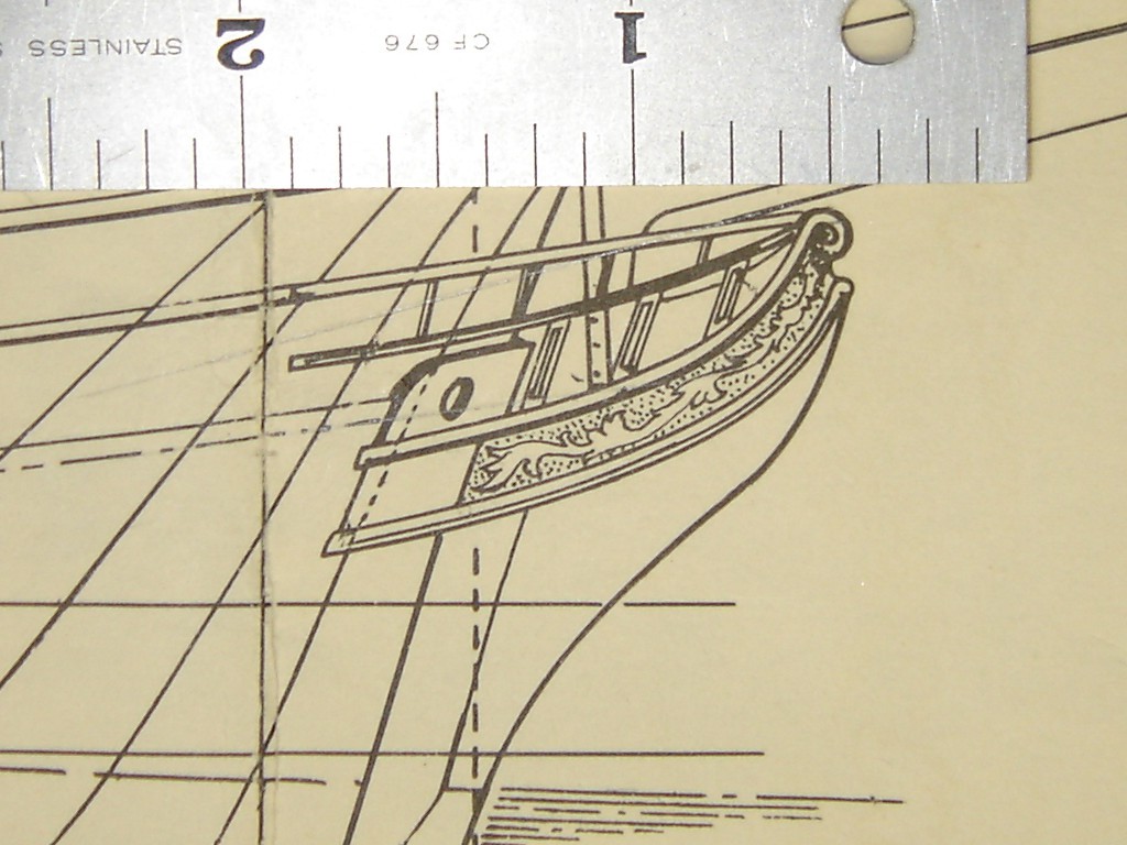
The trail board, which I understood to be flat, looks like it runs from the stem back to a point where the hull has some breadth. I guessed that it might be oriented something like the blue and gold trail board on this model:

Supposing so, then the profile drawing shows a projection of the board leaving two degrees of rotation to determine the correct shape. In between me asking for, and the builder of that model sending another view, he described the boards in a vertical plane. So that's down to one rotation. A first proof of concept demonstrator doesn't have to be actually correct, so I guessed and projected from the drawing to make a solid model. The yellow inch ties model scale to the drawing.
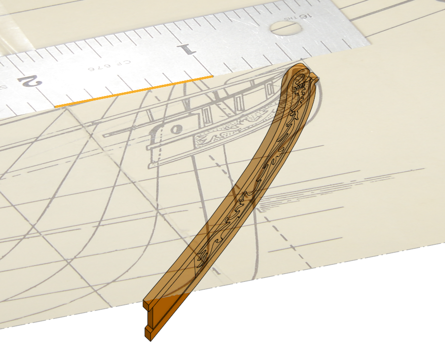
While the ornamental figure has a convoluted outline, it appears essentially flat in the drawing. Maybe the prototype was more viney/leafy and maybe a larger scale drawing would show that. For a first whack, it's convenient to believe that it really is supposed to be flat and extrude the traced figure into a "2.5"D solid.
First articles: port & starboard figures cut from 0.001" brass glued to a chip of hardboard.
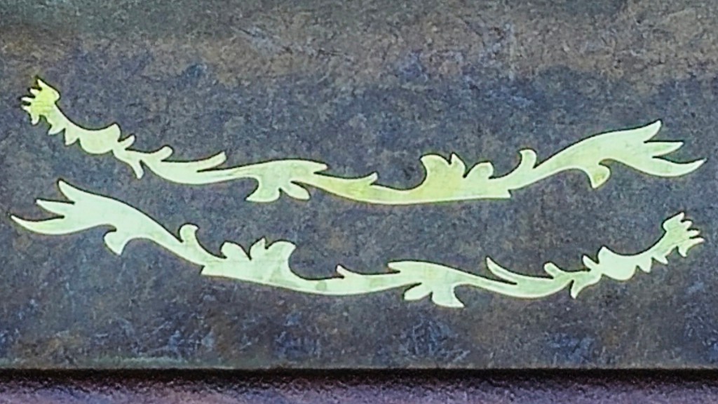
Sharp inside corners were the main challenge. These parts were received as good enough to validate the idea; next try could be sharper. In part because the underlying surface could be more nearly level -- note left end of the upper part vs right end of the lower part.
| aside: | At the Shipwrights' meeting where I handed over the brass figures, one of the members gave a presentation on tracing over images with precision (straight lines, round circles, symmetric symmetries, etc.). He was making decals, but it's all the same problem and process as for tracing e.g. a trail board drawing in a CAD sketch. So that group now has a recorded presentation that's right on point for CAD from drawings and other "analog" references. |
Alternative to cutting just the figure, here's a whole board with the figure & scrolly borders cut from 0.8mm (~0.030") styrene sheet:
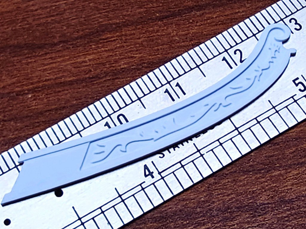
Also well received.
Then, in the course of refining guesses down to usefully correct details, we figured out that a) my guesses were pretty far off, and b) in this case only the figure is needed. So that's probably as far as the whole-board example will go in this case.
Material samples included a piano key top harvested from a dead piano. For a loose test of machinability I cut a couple of backlash test patterns. Or, in this instance, more of a deflection test.
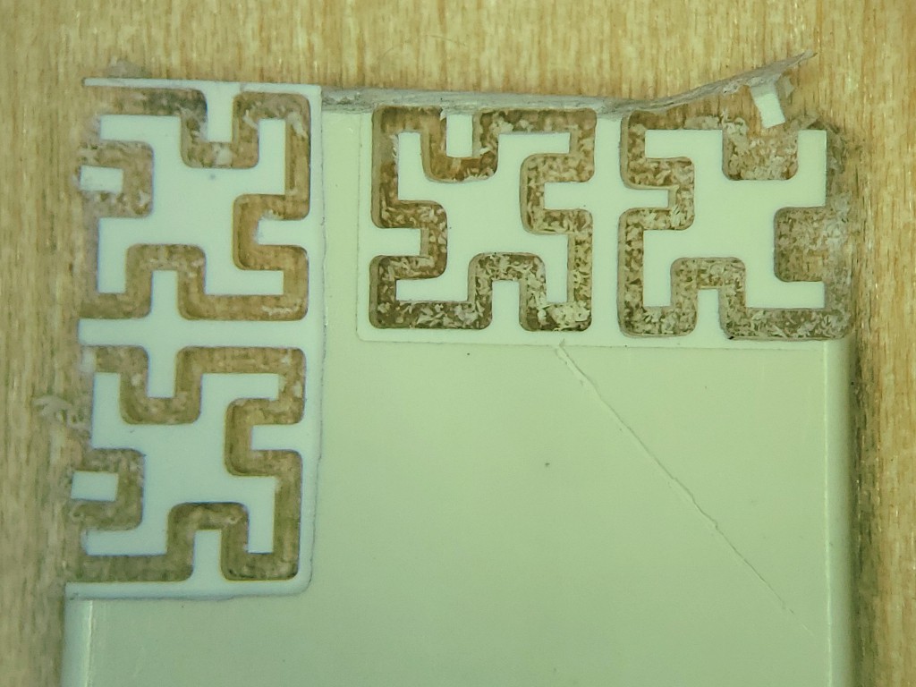
I should keep better notes on feed/speed/doc/etc -- I think I'll remember but don't. The pair on the left were cut more accurately. The pair on the right were cut more aggressively -- successfully but with more evident tool deflection. If you didn't notice, you might appreciate how that could still be "close enough" for some kinds of work. The ragged edge around the left pair was a fat-fingered step down.
Here's the cutout from the top-right corner by itself:
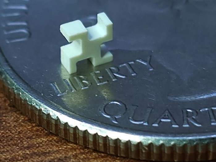
Yes, I know the traditional piano key top material is ... constrained. See me not typing the word into the searchable www. Anyone building for commission probably can't use it at all, and anyone building for their own enjoyment should probably make sure their next of kin know which models they can gift but not sell. And if you find an old piano carcass, keep it among friends (or find more authoritative guidance).
Back to windows
After a little looking at how divided windows are made, I noodled up...
Well, first I had to find a word for the internal dividers between window panes that, being internal divisions and not load-bearing, are not mullions. They're called muntins. I'm pretty sure I'd never heard that before.
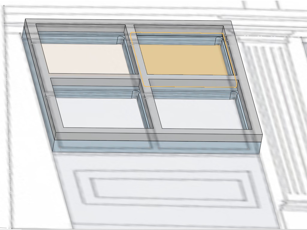
...I noodled up an inner (back) frame with pockets for the "glass" panes and an outer (front) frame to capture the panes in the pockets of the inner frame. For sharp inside corners, I planned to cut the outer frame with a pointy v-bit. The resulting taper would give the outer frame an appearance of thinness and might even look something like glazing putty if painted, so that could be a bonus. For the inner frame I wanted to use a square end mill to cut a clean step in the frame for the "glass" to fit into, but that wouldn't cut the sharpest corners, so that part has "dogbone" clearances for a 0.015" (0.38mm) end mill to overcut the inside corners on a bet that the front frame would hide the overcuts better than it would not hide undercut corners. The recycle bin yielded some flat clear PETE which is fairly stiff with a "glassy" surface. The inner frame pockets are a little deeper than the measured thickness of the PETE.
For a first try, I cut the frame parts from more of the same styrene sheet, cut the "glass" panes from the PETE packaging material, and used thin solvent "glue" for plastic models (mainly styrene) to stick the frame parts together.
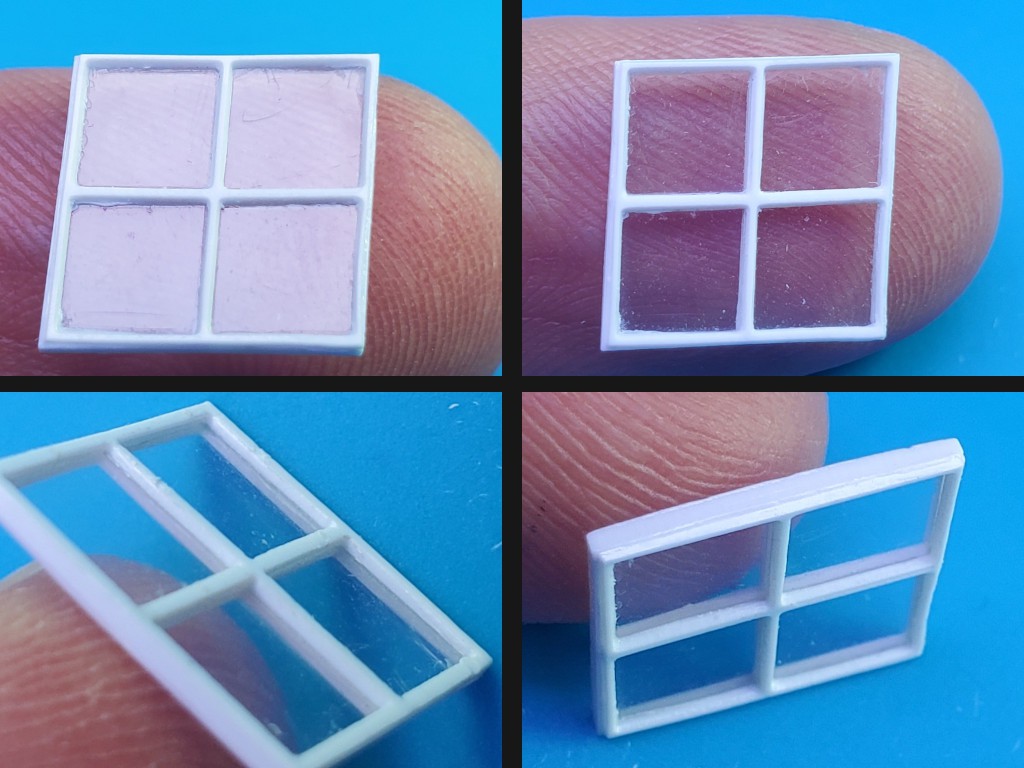
The solvent worked well to wick in between and bond the styrene frames without fouling the "glass". If you look close, you can see where some solvent-softened plastic squished a little when I squeezed too hard on one side. I think that would be not too hard to avoid if doing this again.
As a proof-of-concept, that worked well enough to prove the concept. But unpainted styrene wasn't going to fit well in a wooden ship model and I don't know how to paint that (I suppose the edge seam would be well enough hidden to permit painting before assembly -- if paint thickness didn't screw up fit of panes into pane pockets). Also at this scale the styrene frame is soft enough to be very vulnerable to, uh, plastic deformation. Some bending and straightening may have happened. So that was promising but not really satisfactory.
What other material?
Wood would work well with wooden models. But wood doesn't work well for very small features on the scale of the wood grain. Modelers use boxwood for fine stuff, and indeed I've seen some amazingly fine detail in carved boxwood, but I didn't have any and didn't find any nearby source. In any case, it seems like wooden parts would be frighteningly fragile if possible at all.
FR2 material for circuit boards is brown and made of, or at least was originally made of paper saturated with phenolic resin. So it's not entirely completely unlike wood. After wasting away the copper and most of the thickness of some copper-clad FR2 board, down to 0.7mm for the inner frame and 0.4mm for the outer, I gave that a try.


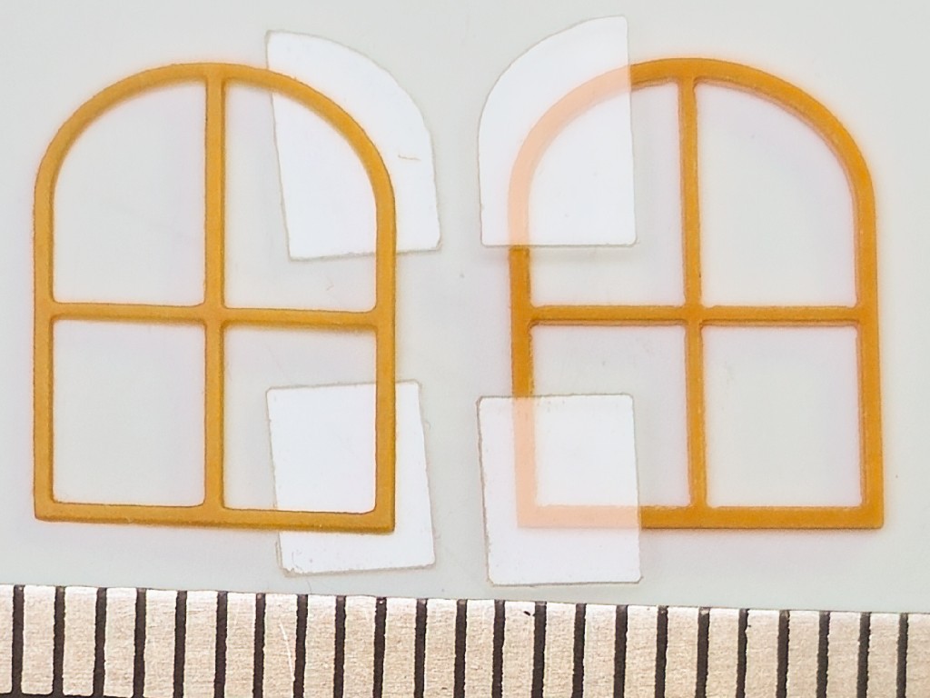
A frame-shaped pocket cut frame-deep into a bit of basswood served as an alignment jig for assembly. I had cut a similar pocket for the white plastic example above. That worked as far as lining up the parts, but having the parts lined up in a hole didn't help much. This time a deeper relief cut across the jig allowed access to spot glue two sides with the frame laid in the pocket, and to get under the frame to pry it out of the jig. The idea was that securing a spot on each side would hold the assembly together well enough to pop it out of the jig to glue around the rest of the edge.
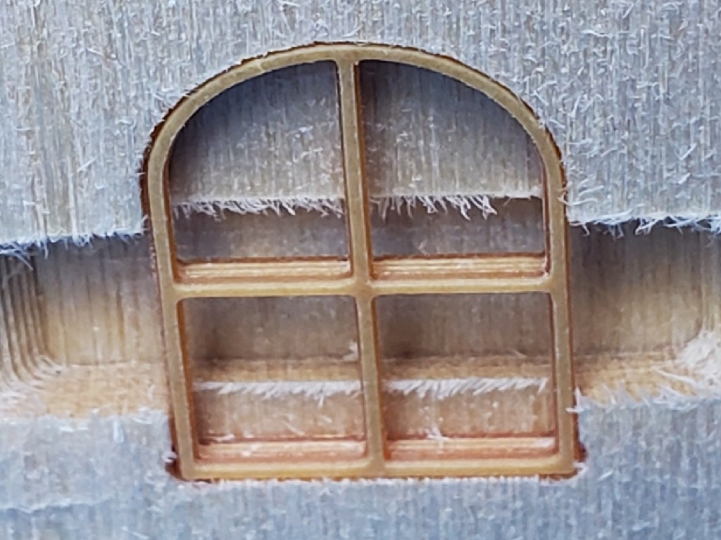
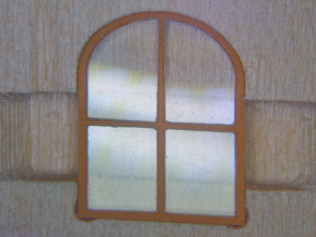
This time I used CA glue for the FR2 material. What I have is not water thin, but thin enough to wick enough between the frame edges. A tiny dab on each side. That was enough to secure the assembly so I could pull it out and glue more of the perimeter. It may have been already glued well enough to never come apart -- especially if it would be going straight into its place in the model bulkhead. But I figured this demo piece would get passed around and handled some, and even if a proof-of-concept piece doesn't have to be right it surely helps if its not broken, and I didn't want to bet that the very thin frames were stiff enough to keep the panes in place while the top and bottom were only cantilevered together from the middle, and, and, and the rationalization is strong in this one. Adding glue along the bottom edge and more of the sides went well enough. If you look rilly close at the pic below you can see where a slightly more than ideal amount of glue wicked along the horizontal muntin, but that's not a very eye-catching flaw.
Securing more of the sides left the top arch less cantilevered. I probably could have stopped there without any trouble (especially in retrospect with future knowledge of the material). But nooo... To finish off the arched top of the frame, I stuck the bottom edge back in the jig where it fit closely enough to stand upright. Handy, right? And >this< close to finished.
Yeah, um...
Here's me remembering that capillary flow is all about not needing any help from gravity:

So after trying to wick away at least some of much too much glue, I decided to quit before making a worse mess and settle for a mostly successful part with a big (relative to small part) booger on top.
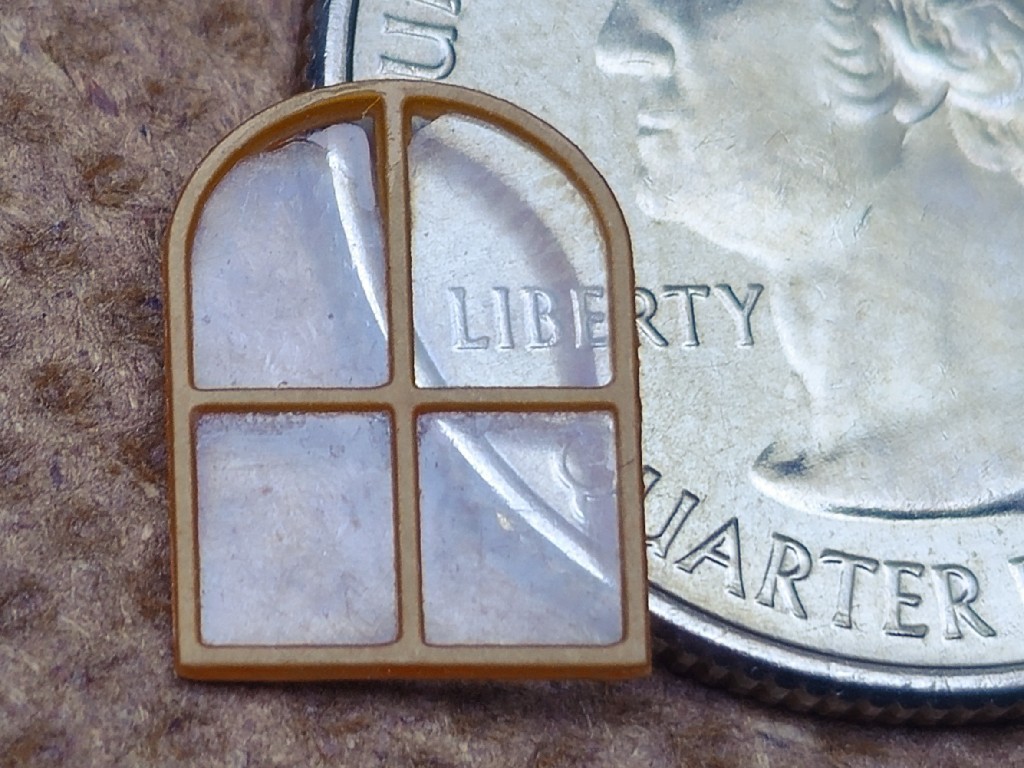
Then I got distracted on a side quest that's probably a better fit for a generic "3018"-type CNC for bigger size with less concern for precision. This is already taking far too long to write up so that will be another log another day (month).
Production
The experimental windows and other parts were well received. Concept proven, it was time to make a usable set of windows per the quarter deck bulkhead drawing up the page.
In the first instance, I tried to copy some key reference lines from the drawing as near exactly as possible. Even with a rough raster image of the drawing, you can still get pretty close by zooming in tight and dropping endpoints in the middles of fat fuzzy regions. Straight lines then matched straight lines, so the practical absence of non-rectilinear distortion gave some confidence. The projection looked no worse than pretty close to square.
So I took the drawing straight from the image for the first trial parts. The three parallelogram-like windows actually have a very slight vertical taper. And the two outboard windows are very slightly taller than wide. That makes all of the divided window panes each slightly different, the frames all have a right-side-up orientation and the outboard windows differ ̶ ̶l̶e̶f̶t̶ port/starboard -- but all the differences are too slight to distinguish, but just enough to be not quite right if disregarded. For the four panes of the white prototype window I just made sure to keep them straight. Getting both the frames right side up was a little more tedious. Lots of this-way-or-that-way to see which fit the jig or each other a little better. I wasn't looking forward to managing a dozen almost but not quite identical little bits of "glass".
I don't know whether that un-squareness was real in the drawing or just distortion of the image.
So I cheated. I tweaked all the near-vertical edges to vertical, narrowing the outboard windows by 0.7% at the bottom, the starboard-inboard window by less. Lifting the bottom edges of the four "square" windows by 1.7% to made the outboard windows equilateral -- so those four frames can be inverted or swapped side-to-side. In other words, all the bits that were similar become identical & symmetric. Including all the little divided panes. Maybe that just undoes a slight distortion of the image of the drawing, I don't know. In retrospect, since the scale is at the bottom I probably should have stretched the top instead of narrowing the bottom. In any case, the differences are pretty small. It's not my model so I hope I don't presume too much by calling them insignificant for this purpose.
But even if all the little panes are multiples of just a few sizes, that's still a lot of little parts.
I imagine a common way to do this is to make the divided frame, and maybe put a bit of "glass" behind it. Since this is all about what could a model maker make differently with a different tool, I set out to make a window with the glass "in" the frame. Maybe that will look less like a frame with a bit of "glass" behind. One of a couple of reasons I started with a real "divided light" of separate panes was concern for excessively fragile, and maybe not very flat muntins spanning the opening. Dividing the panes and wicking glue in between the frames would allow the front & back parts to reinforce each other, and to keep the muntins tight to the "glass". For the styrene example, the frames seemed plastic enough that it's not hard to imagine the skinny muntins on either side of a single pane getting deformed out of flat and leaving a visible separation from the pane. The other reason will come up later.
One happy surprise was that the FR2 material proved more than sufficiently tough at this scale. Not fragile at all and quite elastic. Not stretchy elastic, but more springy than bendy or brittle. With durability and flatness pretty well solved, I ventured to try "fake" muntins front and back spanning single panes. And, in a fit of reckless abandon, slimmed the muntins from ~0.46mm (7/8"; 1:48) to ~0.4mm (3/4"; 1:48).
CAM happens here. I used Kiri:Moto (in Onshape) and G-Code2GRBL for everything on this page.
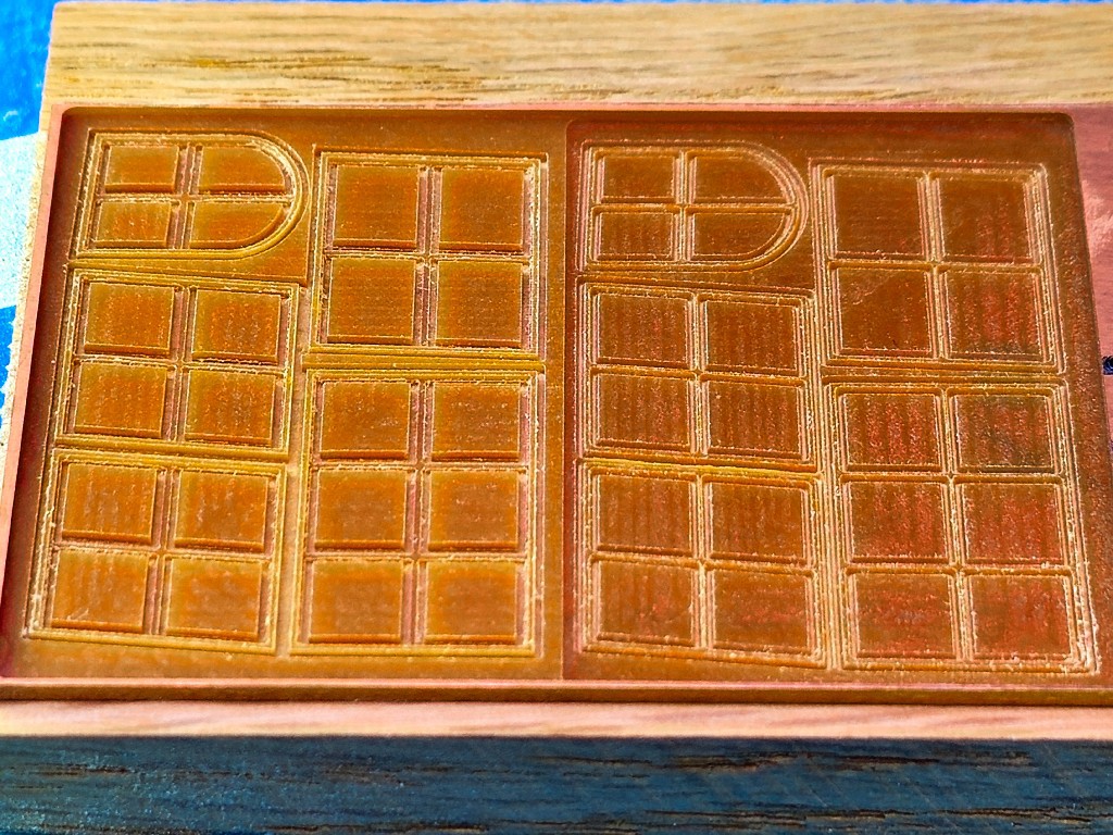
Having gained some confidence in design, material, and process, I felt pretty good about this revision. Here's the whole set cut in one go:
And the PETE "glass":
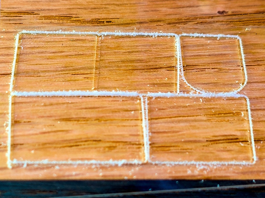
It must be possible to mill PETE more cleanly than this, but I didn't put much effort into figuring that out. The setup I used pushed material to one side of the cut leaving one clean edge. So these are cut in the direction that put the clean edge on the keeper side of each cut. In the photo above, cleaner edges are most visible in the upper left between the pair of outboard window panes, and also on the right side edges of each part in this view.
After no relief around the first jig, then some relief for the second try, this all-up jig has lots of relief around all sides of each window. It holds just the corners to allow gluing up all sides in the jig -- and horizontal to keep gravity at bay. It also supports the interior of each frame so they can be "squeezed" together without distortion.
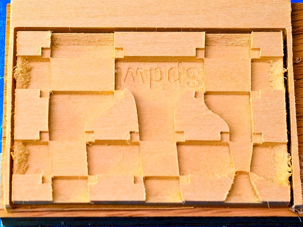
The "corncob" mill I used for this, because it's long enough to cut through the 3/16" board, left lots of uncut fibers on the cross-grain slopes. Contrast with the clean-cut steps in the jig photos above. Just a thing to either remember or re-discover.
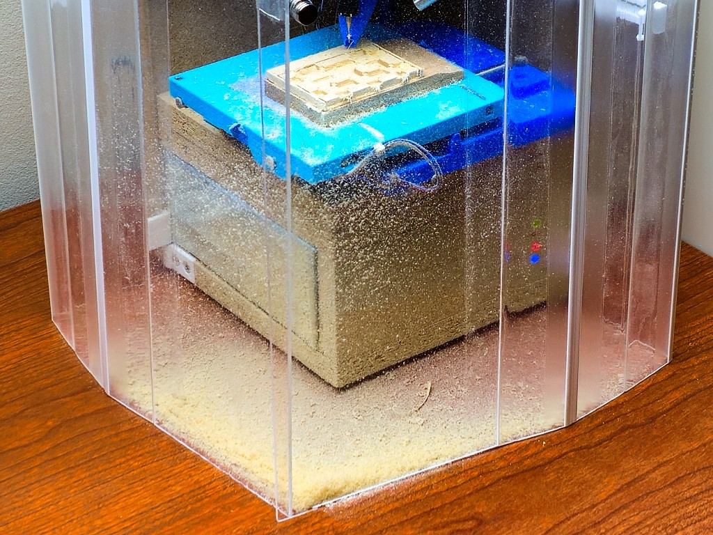
For a little aside here: while this project focuses on the CNC mechanics and not the fancy enclosure, cutting quite a lot of volume (relative to scale) out of that board made for a good illustration of how the enclosure & filtered negative ventilation help to make this a genuinely practical desktop tool:
All the parts:
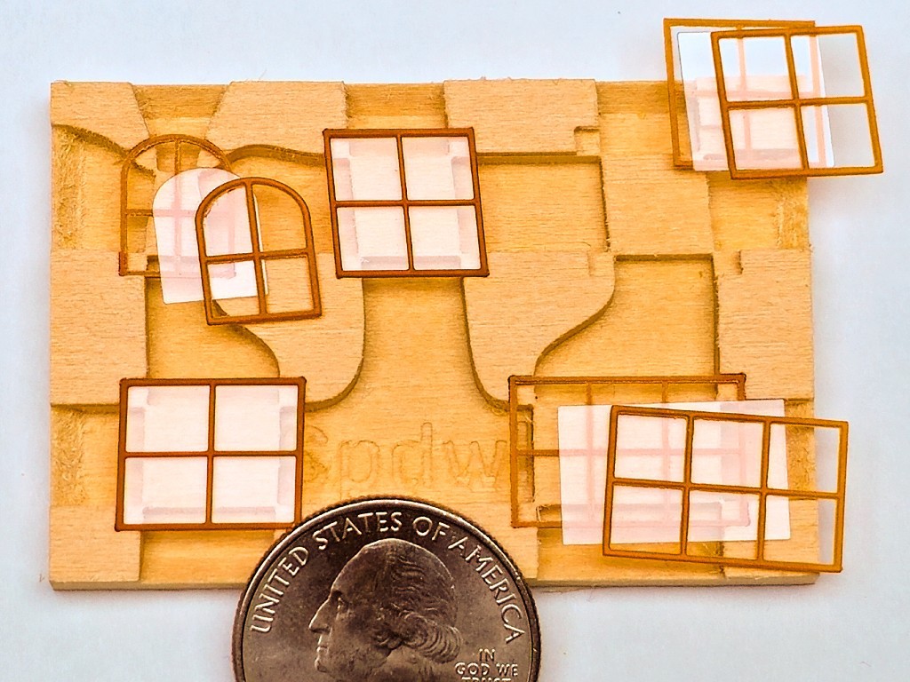
A close look there will reveal that some of the frame parts are more "clean" than others. Bottom-left vs. top-right, for example, and the close-up below:
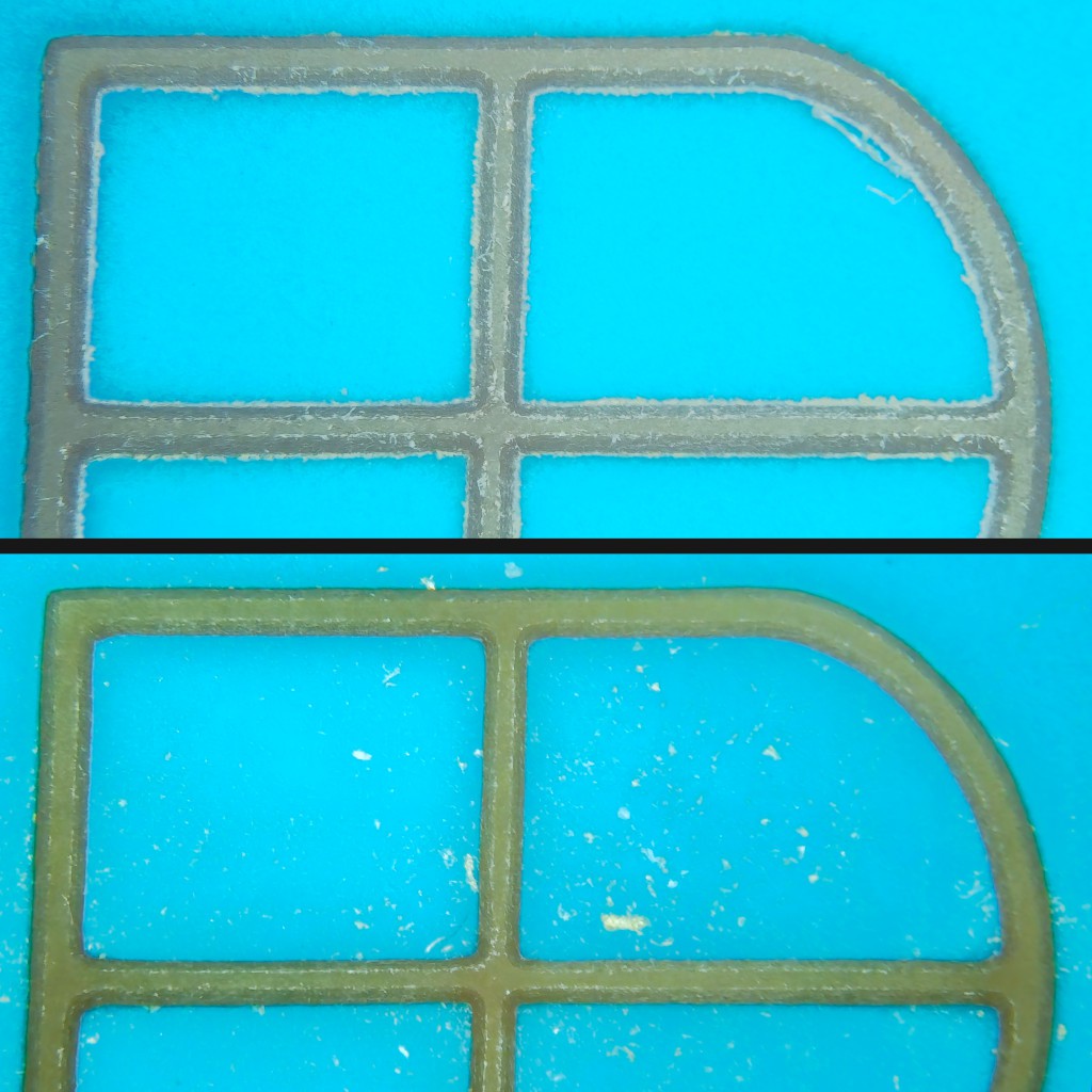
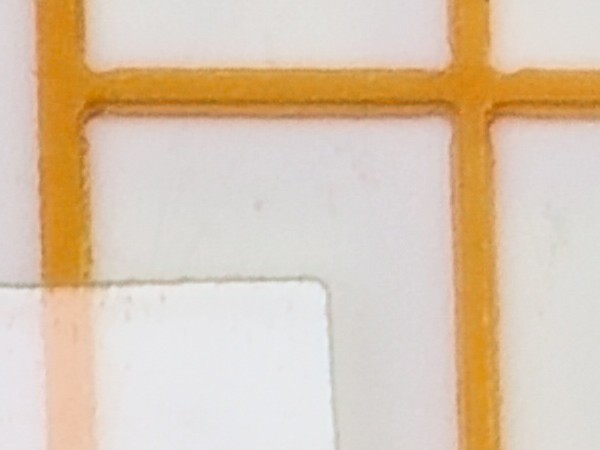
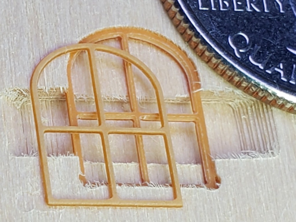
The frames fresh off the mill were a little fuzzy. Especially the front frames because the tip of the V-bit wasn't quite square so it left a little edge similar to mold flash. If I used the same bit again, I could cut a little extra depth through the material to get past the unsquare tip. That would make the frame a little thinner but probably not too much so. The before/after pictures show what came off the machine and then the result after burnishing with the end of a wooden toothpick.
If you didn't immediately notice the difference between "clean" and as-cut parts in the photo with the coin above, then you might see how this post-processing could be optional. I thought it made the parts look better, and this was about figuring out process as I went, so I spent some time with the toothpick and magnification. I figure that's worth showing here for the sake of realistic expectations about part quality and post-processing effort.
Up the page I described one concern that I'd had about trying "fake" muntins spanning a single window pane. Here's the other: would a visible gap between the front and back frames spoil the illusion?
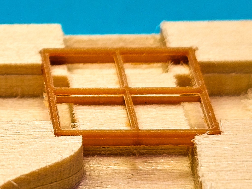 (that's also an as-cut/un-burnished part)
With "glass" in place between the frames, example on the left below, comes another happy surprise: refraction closes the gap.
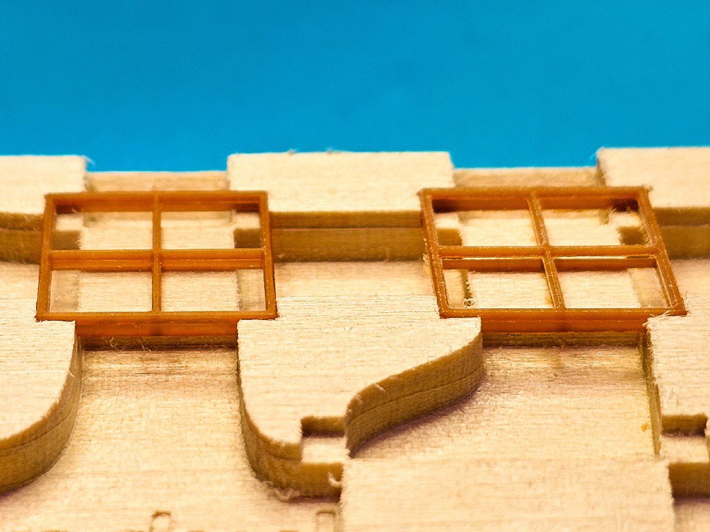
(besides the closed-up gap on the left, this view also shows a burnished frame on the left vs as-cut on the right)
If you've read (or at least scrolled) this far, you get to check out the finished set of five little windows:
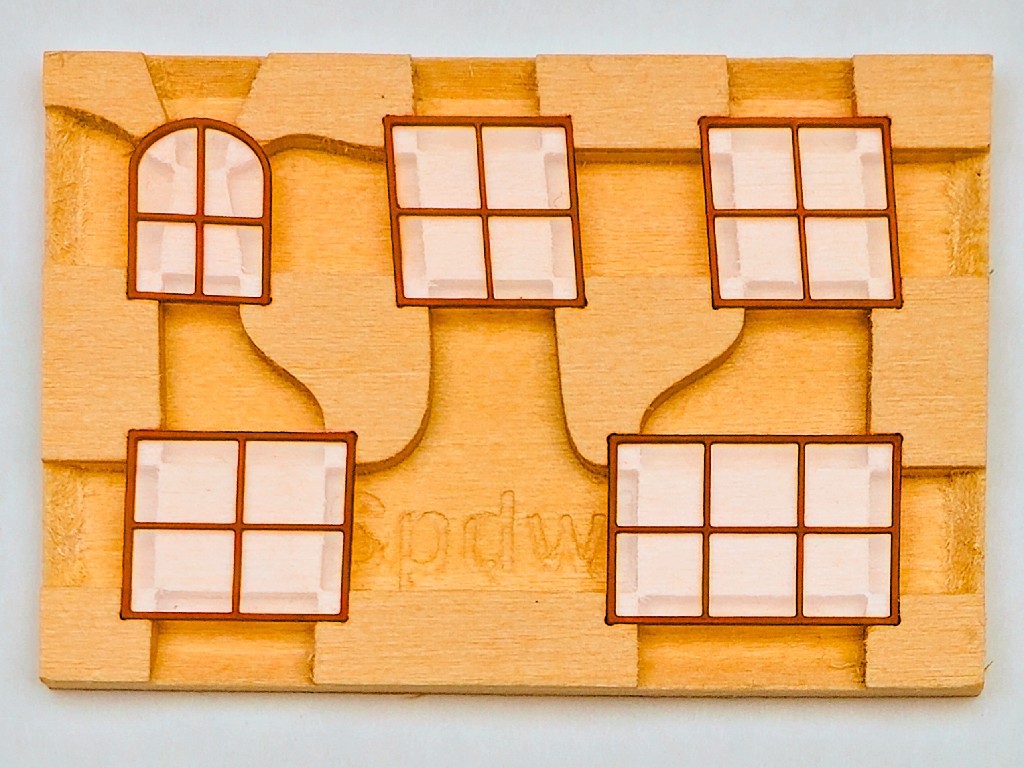
(this set has thinner muntins that the first couple of tries -- except that I missed tweaking the arched window which still has "thick" muntins. That kept catching my eye, and it took me a while to figure out that I had in fact missed the change for that window. sorry, Bob!)
And here's the set layed out on the drawing, with a real ruler over the photographed ruler for scale:
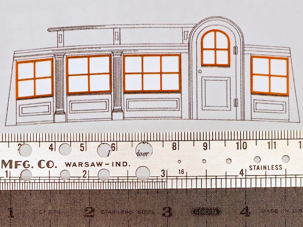
 Paul McClay
Discussions
Become a Hackaday.io Member
Create an account to leave a comment. Already have an account? Log In.