 Paul McClay
Ok, I've been teasing pix of parts of this for half a year...
...while holding out for more of an eye-candy presentation idea. Not least because I don't have a "here, watch this..." video that shows the little machine in its 3d printed form.[a] But no such idea has landed. So, until that happens, here's an eye-spinach look at the latest little differential gearbox.
What's this guy's deal with differentials anyhow?
Well, it's like this...
An early question for an earlier variation on this minimal CNC theme was 'why?'. What (in low budget hobby/"maker" context) could a little CNC do that a laser cutter or 3d printer couldn't? How about a small bevel gear? Laser cutters can make spur gears but not bevel gears. FDM printers can't make precise small features (with a sane nozzle). SLA printers can make small 3d objects -- out of fragile material (tho resins are getting better). So the first differentiating example was a small bevel gear cut from acrylic.
But one bevel gear doesn't count. You can't even tell if it's right, let alone convince anyone it's interesting, without another bevel gear.
(And lemme just say here that those gears mesh intoxicatingly well. The little wobble in the gif above is only an artifact of the hasty setup and running out of duster gas to keep trying to catch video of a really smooth spin. Smooth driving torque against resistance too. It's one thing to read about involute geometry, and quite another to feel a self-made pair of own-design gears defying their coarse appearance. An instance of encouragement to keep the project going.)
So, then, on the road to Shelbyville, as an example of something that more common tools wouldn't have made better more easily in a fraction of the time, that was sufficient. But not satisfying. Giving a pair of gears something interesting to do escalated to giving them more friends and a little differential to live in:
And that was a fairly satisfactory example. For a while. There was that little thing about it ending up not quite as compact as I'd first had in mind because I was having a hard time (i.e. not) keeping consistently small runout... But life could go on.
Until, eventually, I started to get a better handle on runout.
And then, eventually, which is what they called 'later' in those days, I got around to scratching the "not quite as compact as I'd first had in mind" itch...
... and made another, littler differential.
That's still a fine demo wodget. Which, among other widgets, is useful because all this is easier to show than tell. But t's awkward that the catchy video about that shows an obviously different variation on the "Minamil" theme. But I don't have the next eye-candy demo video yet. O the wearying weight of first world problems.
So, that's the first chapter or three of "what's this guy's deal with differentials anyhow?"
And then...
...a couple of things. Two independent events described here in arbitrary order because I don't remember which was first or second and it doesn't matter.
Thing 1
I thought of a use for a cheap little RC car. Online Retail offers heaps of cheap little RC cars and controls that look like what I was looking for, so that seemed like the easy part.
Until, on the cusp of ordering one, I figured out that all the cheap ones use bang-bang control (go, not go, go backward, turn left, not turn, turn right), which would not do, and the jump up to cheapest with proportional control was too much less cheap for the idea in mind.
Until, on the cusp of not ordering one, I stumbled on the D12 Mini -- inaugural product of CXD, a fresh (then) spinoff from an RC brand of some good repute. And also found a source of the real thing (among unequal copies) in simplified packaging for pretty near the same scale of cheap as the cheap stuff.
I'm not here to fanboi, but this is actually quite a thing. It's not every cheap toy that a pack of YT "influencers" will hasten to introduce by naming the designer (Mr. Huang) like anyone watching would recognize and grant automatic credibility to the esteemed person and his new venture.
Thing 2
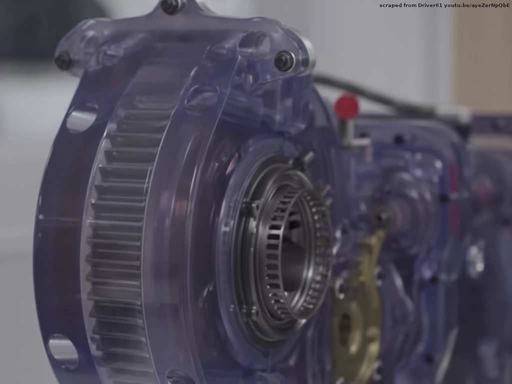
I watched this video by Scott Mansell about F1 (big money race car) gearboxes. However extreme, they are basically kaiju motorcycle gearboxes. So it was mainly interesting for extreme particulars of a basically familiar device. Except for the big final output gear at the back end.
If you already know what I didn't, please feel free to skip down the page.
Puzzle. I couldn't figure where the differential fit between that big midline spur gear and the wheels. Or why it wouldn't be integral. No similarity with anything driving a single wheel was going to help. And they weren't talking about it... and still not talking about it...
Until, eventually, they got to talking about this bit:

(the same clip flashed by in the vid intro, but I didn't have a hook to hang it on at that point)
Look at all that stuff inside the gear! Inside the thin skin of the entirely hollow body of the gear, that is.
I had no idea.
And they still weren't helping because they went straight to talking about the variably limiting limited slip widgetry inside the diff inside the gear body. Now that I know how the diff part works, I can see how it works in that cutaway assembly. But that view didn't help much to learn how the diff part works because it's arranged for us (video audience) to look through the removed part of the part I needed to see to see how the diff works.
Simplified, the differential part of all that looks like this:

Not any new idea -- the Wikimedia metadata for that image cites a 1937 source -- just new to me.
If Mr. Mansell's birth, nurture, and life have unfolded in a sea of examples (bio), maybe there was just no chance that it could have occurred to him to explain the easy part while looking through it to the tricky part.
Or maybe I'm the only one who didn't know about planetary differentials.[b]
In any case, the revelation made an impression.
Narrative gap
It appears that getting this done and published this year will require a gap in the narrative structure. So let's just say that a chunk of the story got lost [Mon Dec 1 20:50:46 2025] btrfs[7805]: segfault at 0 ip 0000565b44894e65 sp 0000a94d20ffd210 error 4 in btrfs[565b4482b000+71000] not a single broken arrow headline and the extradition papers conveniently missing, but el Alcalde "suggested" that the little truck should get a differential anyhow.
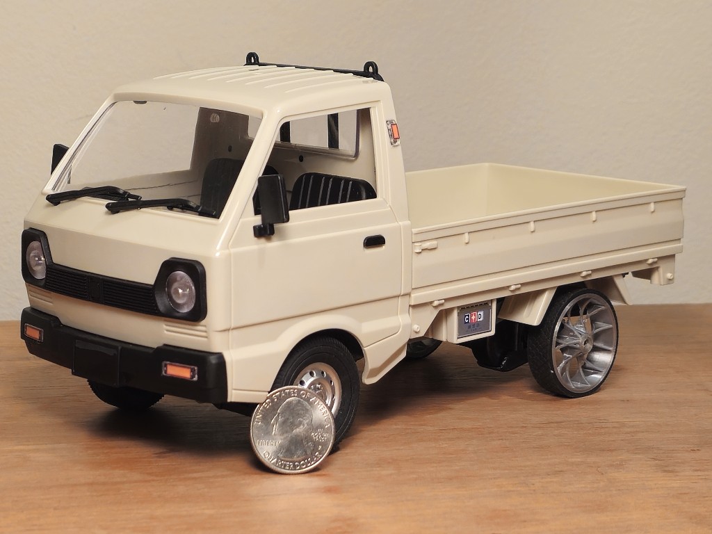
Under the truck
The D12 Mini is a 1:16 scale rendition of the more established D12, which is a 1:10 scale rendition of a particular iconic kei truck.
The underside of a D12 not-mini looks like...

...with a motor and reduction gearbox up front(ish) turning a driveshaft turning the pinion, all longitudinal so far, in a ring-and-pinion rear axle. (mmmm... bevel gears...) As built, that's a solid axle with a plain ring gear. But if you want a differential instead of a solid axle, you can get that from the robust ecosystem of replacement and upgrade parts. Easy.
Under the Mini? Not so permissive.

There's a cosmetic nod to the shapes of driveline parts ahead of the rear axle while a unit integrating a transverse motor, reduction, and the solid driven axle does the work. (It's also sprung w/2dof.)
Space for a differential?
The diff housing "pumpkin" is pretty clearly not where motivation gets to the axle. So perhaps it's empty? If I could shrink the spider gear part of the usual differential arrangement even smaller... then maybe use a hollow jack shaft between the driven gear and a little spider gear cage in the "pumpkin", then send a concentric half-shaft back out to the gear-side wheel through the hollow jack shaft?
That idea did not survive a closer look at the power unit.

No
There's no room for anything to turn with the axle other than what's already there.
But
"Thing 2": that diff memorably inside a gear...
They're even already a thing for RC cars. But not for CXD's "Mini"s.
No
Absurd. That gear is a squeak less than 2mm thick, and the solid body of the gear inside the roots of the teeth is under 14mm diameter. The stack up that has to fit in 1.95mm includes a side of the hollowed out big gear (which also has to support and transmit drive torque to ends of planet axles), clearance, a sun gear, clearance, the near ends of far-side planets, overlap between planet sets; clearance beyond the far ends of near-side planets; the other sun gear, clearance, the other side of the big gear (which also bears planet axles).[c]
But
The idea didn't go away.
Maybe
I tried some things that would have to work to make this work. Like small gears.
I've been using acrylic for little gears. It's probably not the best stuff for the purpose, but it's what I had on hand when I wanted to make the first little gear and it's been working well enough since. Acrylic stock on hand was (being of normal thickness) much thicker than gears that would have to work to make a working diff, which would mean wasting most of it down to sufficient thinness before even starting to cut a gear. Admittedly, that was unappealing more due to impatience than scarcity of material.
Not long before, I had unexpectedly good experience with milling FR-2 board for tough small parts. And stock on hand is less excessively thick, so at least thinning it would go faster.
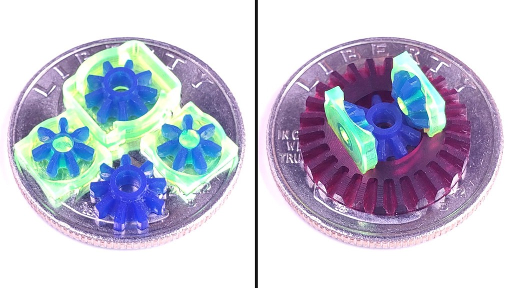
Some little gears -- 0.3 module:
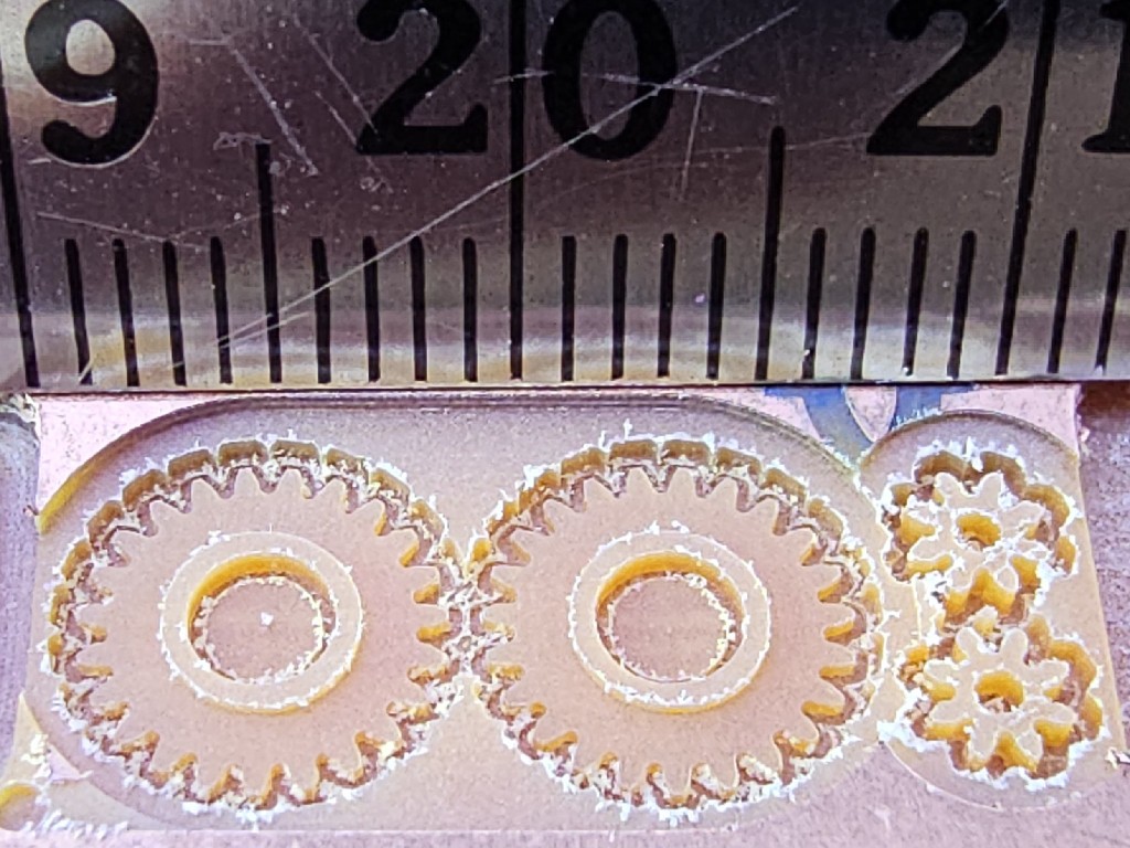 And single sector of what would have to be happening inside a magic differential gear:
 I could rationalize rationale for cutting the not-a-gear body from acrylic, but really it was for the see-thru spectacle.
Stock axles are 3mm steel rod. I had 3mm brass tube on hand, and figured that's at least strong enough for testing the idea and much easier to work with. Freezing the brass and heating the sun gears in hot water seemed to help for press fits that worked well for testing like this -- surprisingly so considering how little contact area there is for the thin gears.
That trial "sector" worked all too well -- on the second try -- so it was no excuse to quit.
Out of order: the first acrylic test part was the pin-in-cup in the top middle of this display group arranged for MRRF.
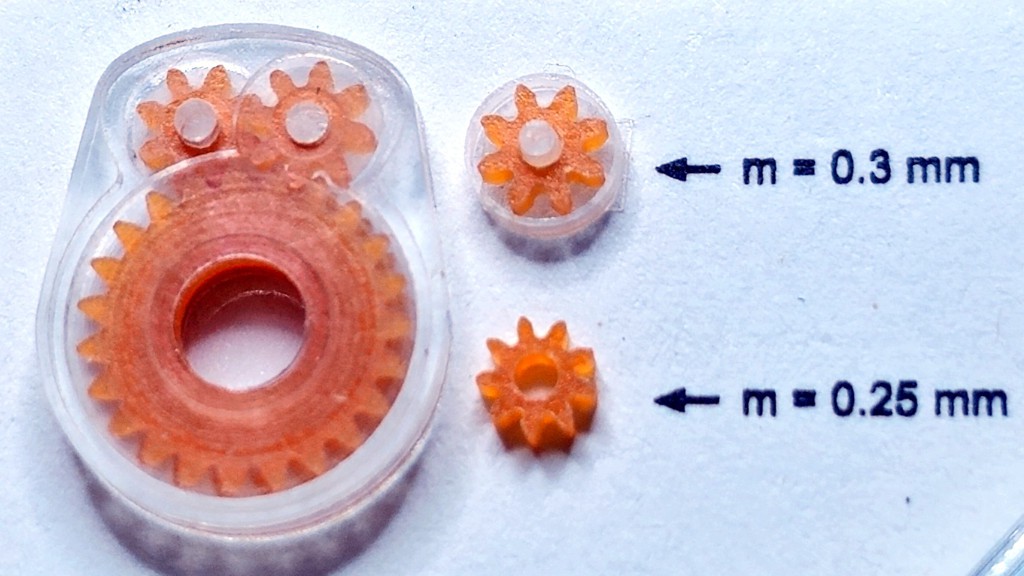
That (the pin-in-cup part) was a test of both the gear/axle fit and also clearance around the points of the gear teeth. There has to be enough clearance around the pin for a free-running fit, and enough clearance around the outside so that there's still clearance when the free fit around the pin allows the gear to move around some. Lesson from the first little differential. However, you can see that "free fit" around the pins didn't mean a lot of slop in this case so drag around the perimeter wasn't a problem. Small round holes & pins are a good demonstration of small backlash.
The big thing on the left in that group was (if I recall correctly) the first test sector which worked well enough to encourage a very slightly altered second try. Printed labels to the right indicate gear "module", or linear tooth pitch divided by π. Conveniently, m * number of teeth gives the diameter of the "pitch circle" (mid-tooth), And the common tooth profile extends m outside the pitch circle, so m*(teeth + 2) gives the outer diameter, and the "big" planet gear spans 3mm tip-to-tip across opposite teeth.
The m=0.25mm gear was a single test part which suggests that smaller is also possible. It's smaller even with one more tooth: 2.75mm outer diameter. An 8 tooth gear would be just 2.5mm across.
Yes
Success with the test sector encouraged trying a complete diff.
In a prior millennium, Ken Thompson wrote about a trip to post-Soviet Russia to fly ex-cold-war fast jets. In an otherwise colorful narrative he wrote: "It was the most amazing part of the flight, but not very spectacular to write about" then briefly stated an event that was surely more amazing to experience than spectacular to read about. [d]
I think this little widget is really neat. In person it has proven to be an effective ambassador to communicate "the point". Expecting/hoping so, I hustled to get a couple done for MRRF -- one to hide in the opaque drive unit where it could prove its function, and one to examine up close for the 'wow' impression. It does that.
But while working on it, I didn't see (i.e. didn't perceive) much that looked like an interesting photo or video opportunity. After finishing, video of the truck in motion would be remarkably uninteresting. YouTube reviewers offer lots of clips of D12 Minis spinning, sliding & "drifting" (loosely interpreted -- apart from a couple of gyro-add mods). This one just drives around with zero drama. Yawn. I can't even provoke interest with a bold claim that it's the diff that makes the difference, not the wheels (tho I like thinking it's the diff). A competent RC driver maybe could demonstrate more precise placement at higher speeds which could possibly sweeten the viewing a bit (if I did the A/B work to assess that it's the diff not the wheels). The best I can do is just to not show it being so sloppy (when over-driven -- it's a scale model not a race buggy). Shrug.
I can type "planetary differential inside the body of a 1.95 mm thick 30t 0.5 module gear", but I don't expect that to make a memorable impression for many readers. Not even if I push it to "with four planet pairs" or "that's ten gears, yo". So I still don't have a current demo video, and, after punting to illustrated text, I fear the "good part" here will be not very spectacular. But anyhow...
Here's a "big" gear made after the trial sectors proved workable. This may be the best "pretty picture" to show the scale and quality of parts, but I've already posted it a few times.
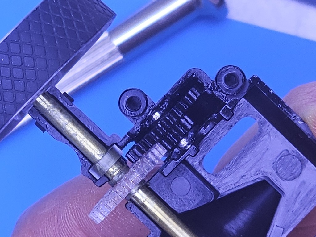
This not-very-thrilling photo looks a lot like the "close look" pic up the page, except for brass and clear-ish instead of steel and black parts:
Oh, and the "tires". My subs came from the paper path of ... I think it was a fax machine. They're almost exactly the right size -- so just slightly stretched to get closer to really exactly the right size. You can see the 3d printed wheels in the first photo of the little truck up the page. They're kinda fun but this isn't about that. The stock wheels are pressed onto the axle ends and I didn't feel like messing with that.
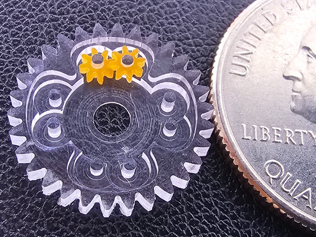
Anyone doing epicyclic gear mesh math while reading this far might be comforted so see this set of gears:
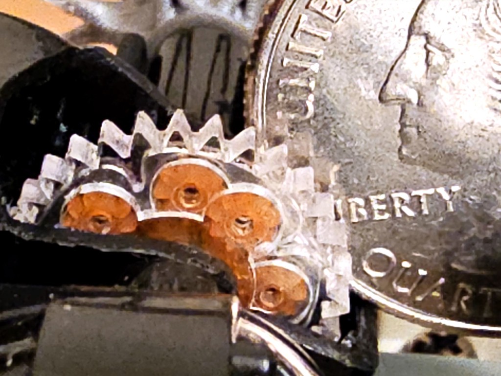
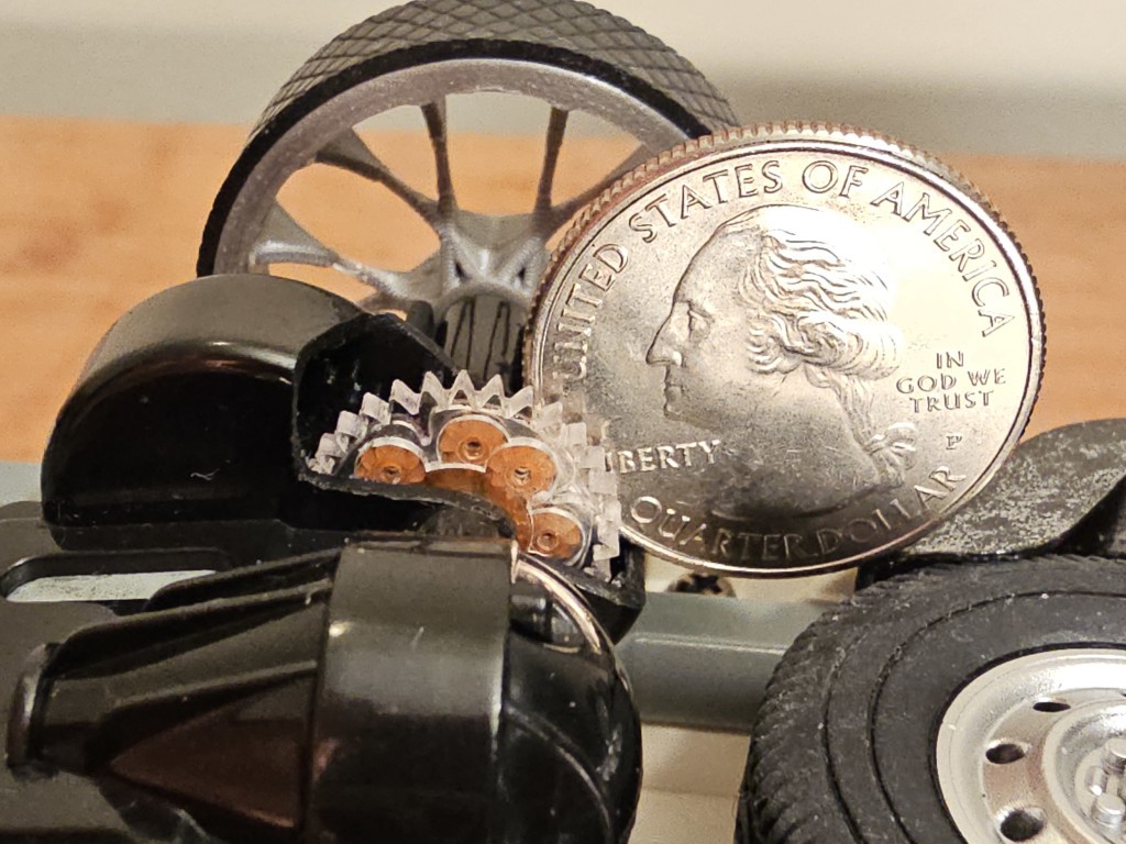
 In an effort to make the fruit of this labor not entirely invisible, I ordered a second motor/axle unit to carve up for a look inside. Here's a wider (less cropped) view of the in-context photo at the top of the page:
A really close look might reveal this "big" gear body differs very slightly from the one in the "pretty picture" above. When the first one worked with an opposing pair of planet pairs, I declared success, because if the second pair (of the first pair of pairs) worked, then of course the rest would too. Later, while trying to add the other pair or planet pairs, I remembered a question that I'd deferred earlier (i.e. an assumption made and forgotten). That thing about mesh math. So that (first) one still has only two planet pairs. It works great. The benefit of more planets is for each to bear a smaller fraction of the load. Fewer planets (two or three pair, because one pair leaves unbalanced mass and forces) would be easier / faster to build, but I went for more as a hedge against frailty of tiny gear teeth and untested material. As it happened, or has happened so far, they're not frail. Until (relatively) recently I had the two-planet-pair diff in the truck where it's underpopulation was modestly hidden inside the opaque motor/axle unit. That means that it's the one that has suffered the most violent abuse (in operation). No problem. I don't know if it would ever wear out or break, but until it does the fully populated diff now installed in the peek-a-boo axle shell is really just a show piece for conspicuous complexity. Just don't tell anyone.
One moving picture
Buried way down here. This might be the most dramatic presentation, in lieu of the video that doesn't exist. Yay motion, but no scale so it can't really stand alone.

In that view: the near-side wheel, out of frame up & to the left, is directly connected to the visible near-side sun gear as both rotate ccw. The near sun gear visibly meshes with two of the planet gears, which in turn mesh with two more planets which are offset away from the near side so that they do not mesh with the near-side sun gear but instead mesh with the obscured far-side sun gear, which is further offset so that it does not mesh with the naer-side planets but is free to be driven cw by the far-side planets. The visible far-side wheel is directly connected to and shows the cw rotation of the far-side sun gear.
Grab the CAD
Curtainfall
Those gears were enclosed for good reason. Otherwise they'd be picking up, and getting wrapped up in, anything the little truck rolled over that wasn't hard clean flat floor.
So here's a snap-fit cover to keep this wonder out of sight:

Epilogue: LSD?
(limited slip differential)
An occasional joke about one of the little demo differentials is that next I should make a limited slip diff. It's funny because of course not.
But... something I read about variations on this planetary diff theme...
But not a concern because this little truck doesn't make enough torque to spin a wheel so badly that I'd ever care.
But the motor is a standard size and other motor makers make different trade-offs to get different results out of the same volume...
Nah. Not gonna waste any cycles on any of that.
Today.
Endnotes:
[a] Only a short stab in that direction, which doesn't and wasn't meant to do the job.
[b] But, if you want to know more, "planetary differential" is an awkward search term because when people writing about planetary gearing write "differential" they're almost never talking about driven axles of motor vehicles. Planetary differentials are also be called "spur gear differential", but that's also awkward for search because they're almost never the subject of anything about spur gears, nor must they be made with spur gears (vs. helical). It appears that the concept just doesn't get much press at all.
[c] For completeness: there is room for more substance to support the "near" ends of "far-side" planet axles; there is also room for the gear to grow a little more thick toward the inboard side. I may or may not get around to saying more about that elsewhere in this log entry.
[d] Bell Labs seems the more authoritative site, but that copy has lost the beginning of the text. This alternate source is unknown (to me) but has the whole text.
Discussions
Become a Hackaday.io Member
Create an account to leave a comment. Already have an account? Log In.
Everything about this is absurd! The parts are sooooo small! If I were you, I would go even further and actually design a D12 mini from scratch using metal. It seems like you have made a tool that is capable of making parts at the desired scale, so why not?
Are you sure? yes | no
Pretty crazy isn't it? Not even remotely imagined at the start.
A full truck night have to be a "sub-mini". The length of the cargo bed looks like the biggest dimension. if I'm figuring right, I'd have to go down to ~1:30 scale to get that under 75mm.
Totally your fault if I end up down that rabbit hole... ;) of course
Are you sure? yes | no
Should scale truly become a problem, you can break parts too large for the CNC into smaller parts that can be connected... or use a bigger CNC for said parts.
Always start by making the fun parts and worry about the rest later. :)
Are you sure? yes | no