I moved everything needed to my own repo: https://gitlab.com/shaos/marina
For example this is my own location of original blink program:
https://gitlab.com/shaos/marina/-/blob/main/blink/blink.c
If you look into function void configure_io() you may see how IOs are configured:
- from reg_mprj_io_0 to reg_mprj_io_6 (somebody said up to reg_mprj_io_7) are occupied by the system;
- then up to reg_mprj_io_35 could be used by user (and may be even reg_mprj_io_36 and reg_mprj_io_37 - so it's like 30 IOs).
//  ======= set each IO to the desired configuration =============

    //  GPIO 0 is turned off to prevent toggling the debug pin; For debug, make this an output and
    //  drive it externally to ground.

    reg_mprj_io_0 = GPIO_MODE_MGMT_STD_INPUT_NOPULL;

    // Changing configuration for IO[1-4] will interfere with programming flash. if you change them,
    // You may need to hold reset while powering up the board and initiating flash to keep the process
    // configuring these IO from their default values.

    reg_mprj_io_1 = GPIO_MODE_MGMT_STD_OUTPUT;
    reg_mprj_io_2 = GPIO_MODE_MGMT_STD_INPUT_NOPULL;
    reg_mprj_io_3 = GPIO_MODE_MGMT_STD_INPUT_NOPULL;
    reg_mprj_io_4 = GPIO_MODE_MGMT_STD_INPUT_NOPULL;

    // -------------------------------------------

    reg_mprj_io_5 = GPIO_MODE_MGMT_STD_INPUT_NOPULL;     // UART Rx
    reg_mprj_io_6 = GPIO_MODE_MGMT_STD_OUTPUT;           // UART Tx
    reg_mprj_io_7 = GPIO_MODE_MGMT_STD_OUTPUT;

    ...

    reg_mprj_io_37 = GPIO_MODE_MGMT_STD_OUTPUT;

    // Initiate the serial transfer to configure IO
    reg_mprj_xfer = 1;
    while (reg_mprj_xfer == 1);
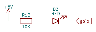
At the end of the function you can see how it sets those configuration values to the actual hardware. Before calling this function it's also setting up the only GPIO pin (that is connected to LED in efabless "mother" board):
    reg_gpio_mode1 = 1;
    reg_gpio_mode0 = 0;
    reg_gpio_ien = 1;
    reg_gpio_oeb = 0;
It's basically means OUTPUT and it must be OUTPUT (inverted indication):

Then to switch LED On we need to write there 0 and to switch LED Off we need to write there 1:
	while (1) {

        reg_gpio_out = 1; // OFF
        reg_mprj_datah = 0x0000002a;
        reg_mprj_datal = 0xaaaaaaaa;

//		delay(50000);
		delay(2000000);

        reg_gpio_out = 0;  // ON
        reg_mprj_datah = 0x00000015;
        reg_mprj_datal = 0x55555555;

//		delay(50000);
		delay(2000000);

    }
Here also clearly visible way to program IOs - reg_mprj_datal covers lower 32 bits, and reg_mprj_datah cover higher 6 bits (if it's defined as inputs you can read from those variables as well).
In this case on-board custom logic is not connected to anything - everything is controlled by RISC-V programmatically, but what if we need to connect IOs to user custom logic? Then IOs must be configured to one of this settings:
//      GPIO_MODE_USER_STD_INPUT_NOPULL
//      GPIO_MODE_USER_STD_INPUT_PULLDOWN
//      GPIO_MODE_USER_STD_INPUT_PULLUP
//      GPIO_MODE_USER_STD_OUTPUT
//      GPIO_MODE_USER_STD_BIDIRECTIONAL
//      GPIO_MODE_USER_STD_ANALOG
But then Caravel RISC-V will not be able to read or write IOs, so what can be done to programmatically write user inputs and read user outputs? TinyTapeout discord user anish experimentally found bits that need to be set for this:
#define GPIO_MODE_MGMT_CONTROLLED_IO 0x00F
#define GPIO_MODE_USER_CONTROLLED_IO 0x00E
So we set user custom design inputs to GPIO_MODE_MGMT_CONTROLLED_IO and user custom design outputs to GPIO_MODE_USER_CONTROLLED_IO (Note: I gave those macro names. Names proposed by anish were different). Now we can build custom tester of on-board custom logic:
https://gitlab.com/shaos/marina/-/blob/main/shaos_test1/main.c?ref_type=heads
 SHAOS
SHAOS
Discussions
Become a Hackaday.io Member
Create an account to leave a comment. Already have an account? Log In.
Forgot to mention that efabless added some simple functions to print stings, hexadecimal and decimal numbers to serial output through FTDI chip on "mother" board (from PC side it's 9600 COM-port).
Are you sure? yes | no