Close
0%
0%

Felini - Revolutionary Pocket-Sized Electronic Lab

Extremely affordable pocket-friendly, designed to provide a wide range of hardware testing and debugging functions in a compact and low-cost

Similar projects worth following
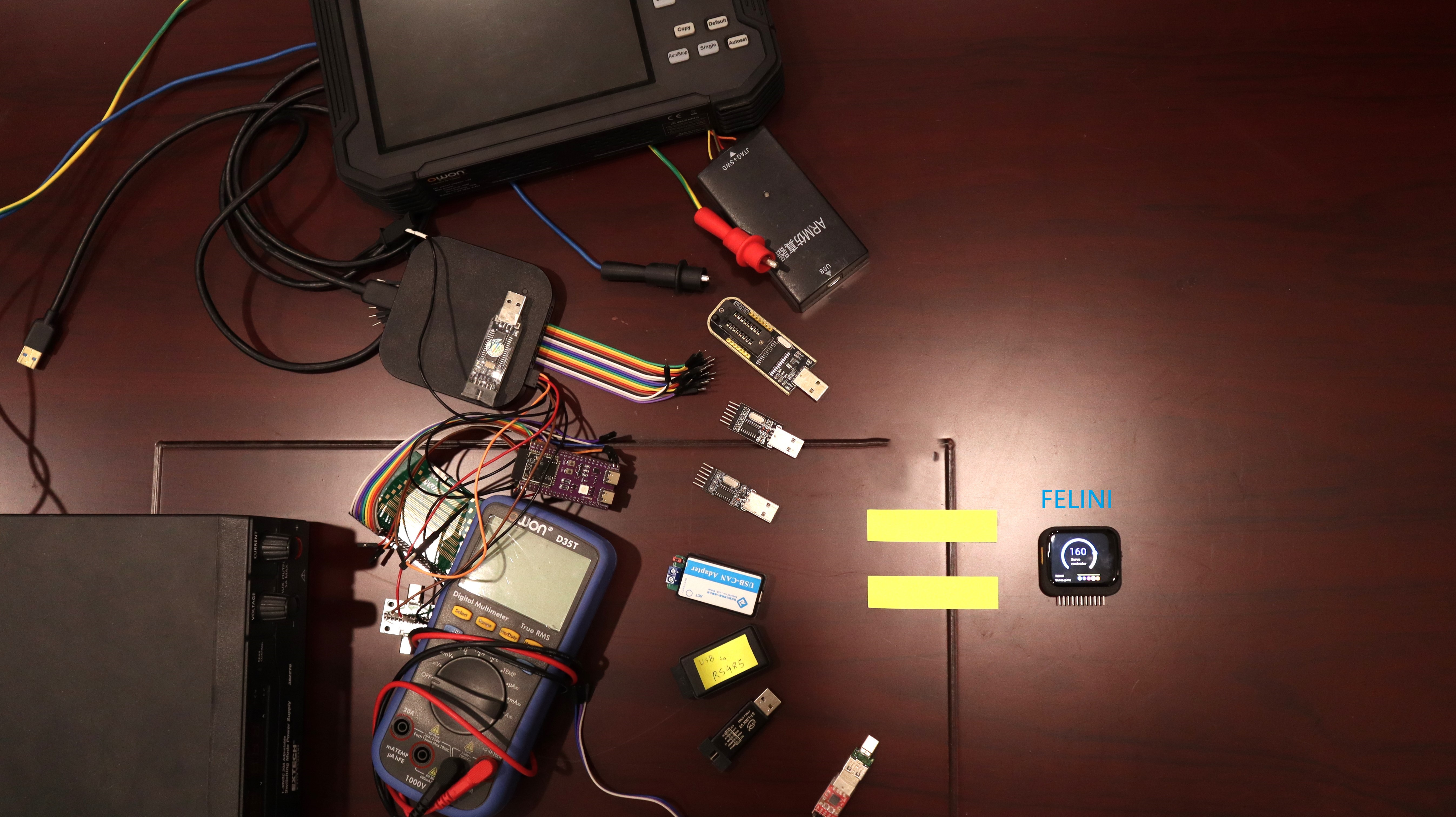
Felini - is a compact device for experts and electronics enthusiasts alike. Just like a Swiss army knife, Felini is designed to efficiently replace multiple common tools in the electronics field.
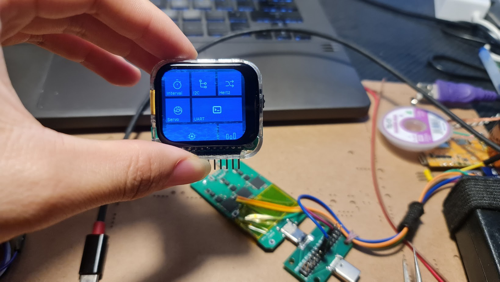
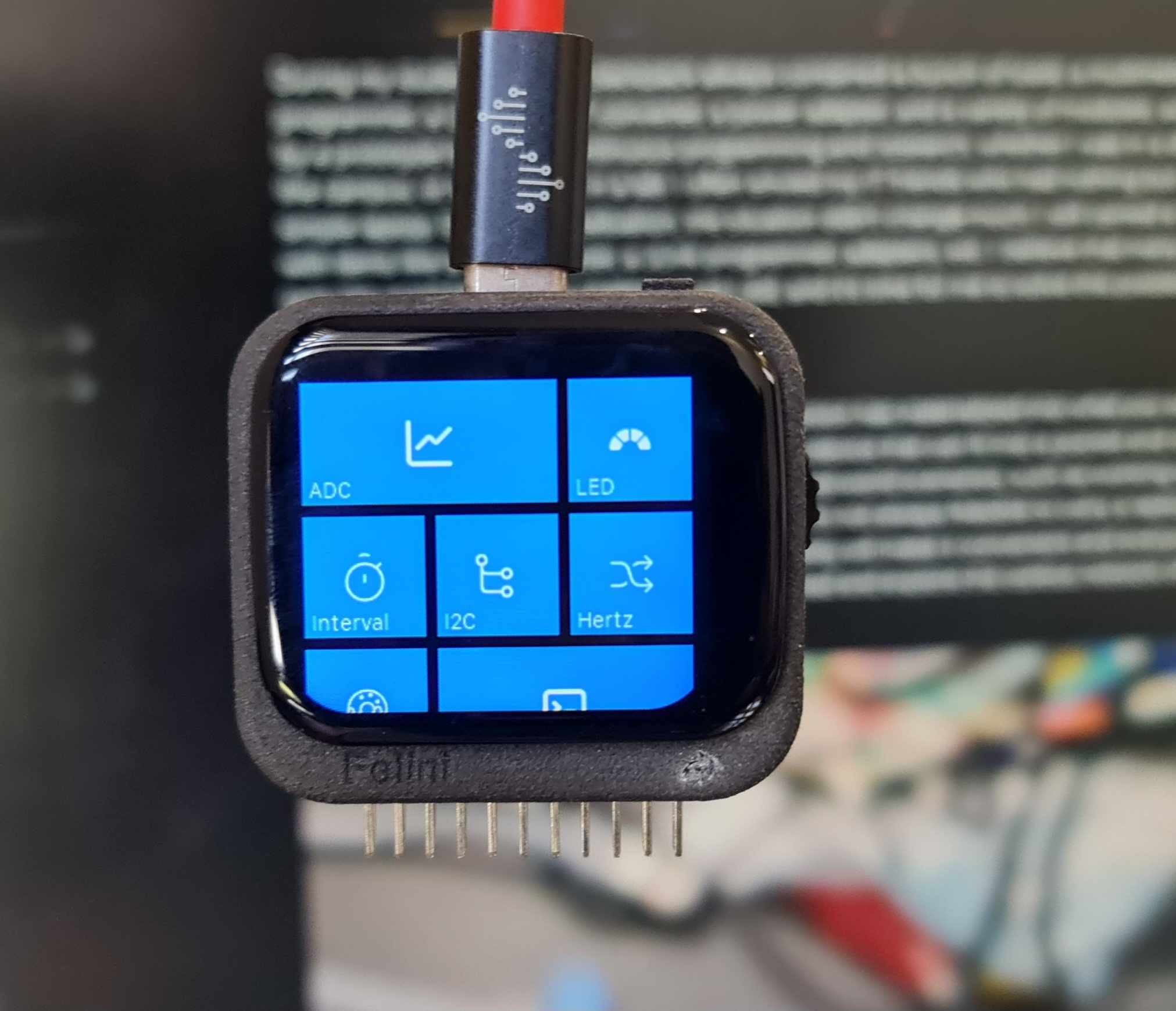
The visual interface for transitioning between tools is similar to applications on a smartphone, without toggle switches, without menus using complex and obscure buttons. Felini is the beginning of a revolution in multi-tools and multi-meters.
Now, you can see the entire project resources here
https://github.com/obitvn/felini-firmware
https://github.com/obitvn/felini-hardware


The story behind this project

In the past decade, we have utilized our superpowers to address various issues all around the world, whether it be creating tools to assist people with disabilities, traversing the depths of the ocean with exploration robots, spanning across rivers and swamps with environmental sensor networks, or harvesting energy from every corner of the Earth, sometimes connecting with satellites in distant skies. But now is the time for us to turn around and craft tools for ourselves. And good tools are the foundation for creating great projects.

During my student days, my backpack always contained a bunch of tools: a multimeter, a programmer, a USB to UART converter, a power adapter, and a variety of modules, accompanied by a prototype board for continuous programming and research, whether I was in a dormitory, on the campus, or somewhere in a lab. I often envied my IT friends who had nothing but a sleek and simple laptop. Even after graduation, the situation didn't change much; I still carried a small toolbox with items like a logic analyzer, a JLink programmer, adapters, etc. I believe that many people all over the world face similar challenges as I did, and it's time for me to solve this problem.

HACKADAY project goals

After several months of iterations, the project's vision has materialized into what you see in the project's images. My goal is to create a compact device that can fit into a pocket and operate independently without the need for a laptop. In real-world scenarios, such as working with robot circuits, car systems, or indoor sensor networks, it's not always feasible to carry a laptop around. The device's small size and standalone functionality will make it convenient and everyone's favorite pocket companion. For instance, I can read and explore the Canbus network of a hotel even while traveling!
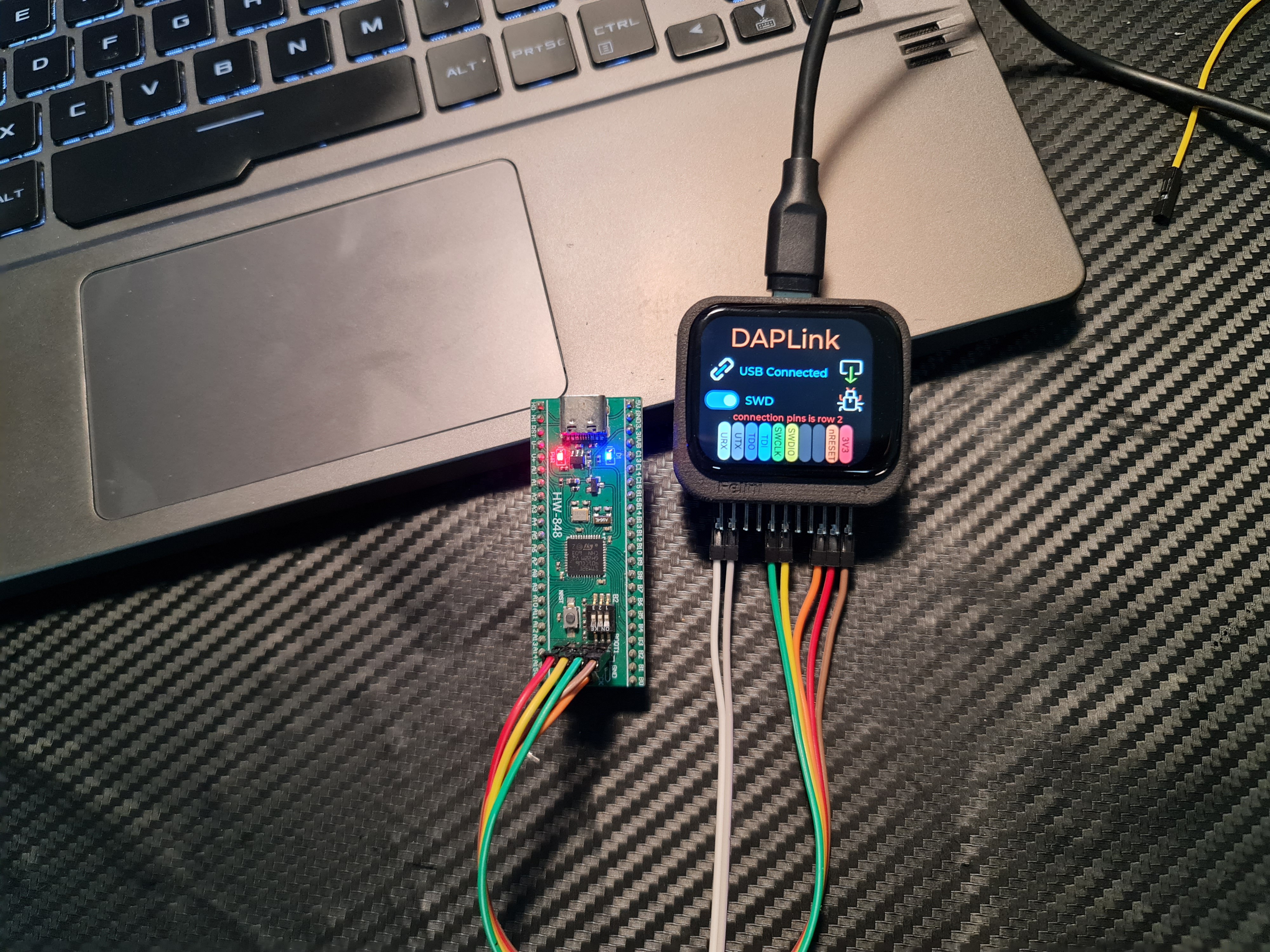
When returning to the laptop, it should seamlessly integrate with the laptop to fully leverage its inherent capabilities. In the past, we've had "multi-functional" devices like Bus Pirate, JTAGulator, FT2232, etc. However, these devices always required accompanying schematics and pinout diagrams, which proved to be quite inconvenient. I don't want to spend additional time browsing the web and searching for this information before plugging the dupont cables into the device. That's why with Felini, the pin map for connecting the wires will appear directly on the screen, making the process much smoother and hassle-free.
Compared to the initial ideas, Felini has been simplified to be more budget-friendly. The Felini project aims not only at engineers but also at being a user-friendly tool for students. Some common features like DAPLink, Logic analyzer, signal generator, USB to UART/I2C, which do not require external hardware, in the future, when the USB control command stack is completed, can be fully deployed on any affordable esp32 kit available on the market. For the full version of Felini, everything is open-source, from PCB fabrication, SMT component assembly, to enclosure fabrication, all can be done at JLCPCB. Therefore, anyone passionate about electronics can create their own version.

This project is also 100% open source, from a different perspective, as it can directly load firmware through the USB port without requiring any additional hardware, FELINI can be used as a development kit, compatible with both esp-idf and Arduino, allowing students to learn and innovate on an open-source platform. With some minor customizations, such as removing the 2.54mm connector, FELINI can become a wearable MHI or a smartwatch with accelerometers and a display. It can also serve as a health monitoring device for the elderly or a handheld terminal device. It all depends on your abilities. With a cost of only around $50, FELINI is likely a suitable device for many people.

Specs & features
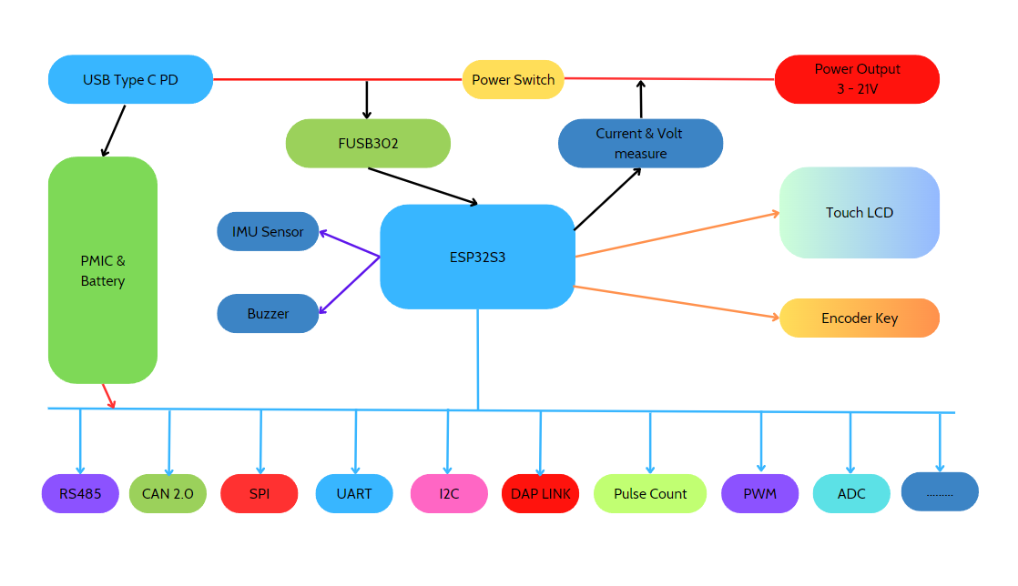
So what can Felini do? Felini was created after three trial versions, striking a balance...

Read more »

PCB_Felini_altium.rar

pcb design file, you can download it here or on github

RAR Archive - 4.71 MB - 10/10/2023 at 07:41

Download

FeliniV2.rar

Gerber file for pcb fabrication

RAR Archive - 157.09 kB - 10/10/2023 at 07:39

Download

felini_model_case.rar

RAR Archive - 12.13 MB - 10/08/2023 at 12:42

Download

felini-beta-08102023.bin

Demo firmware for Felini (beta version)

octet-stream - 2.69 MB - 10/08/2023 at 12:40

Download

felini_vscode.code-profile

vscode profile

code-profile - 53.67 kB - 10/08/2023 at 12:38

Download

View all 9 files

View all 19 components

  • Behind the Hackaday Prize 2023

    Chu Tien Thinh (obitvn)11/26/2023 at 01:37 2 comments

    The new hardware version utilizes the RK816 PMIC IC, adding IR control for learning commands and controlling devices.
    It also incorporates a dedicated Si5351 for PWM signal generation and a Max98357 to enable Fenilni to produce audio like a phone, eliminating the buzzer with beep tones, making everything truly audio-oriented. 

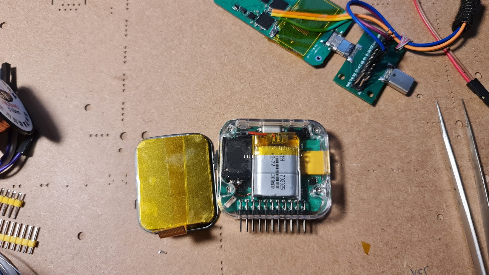
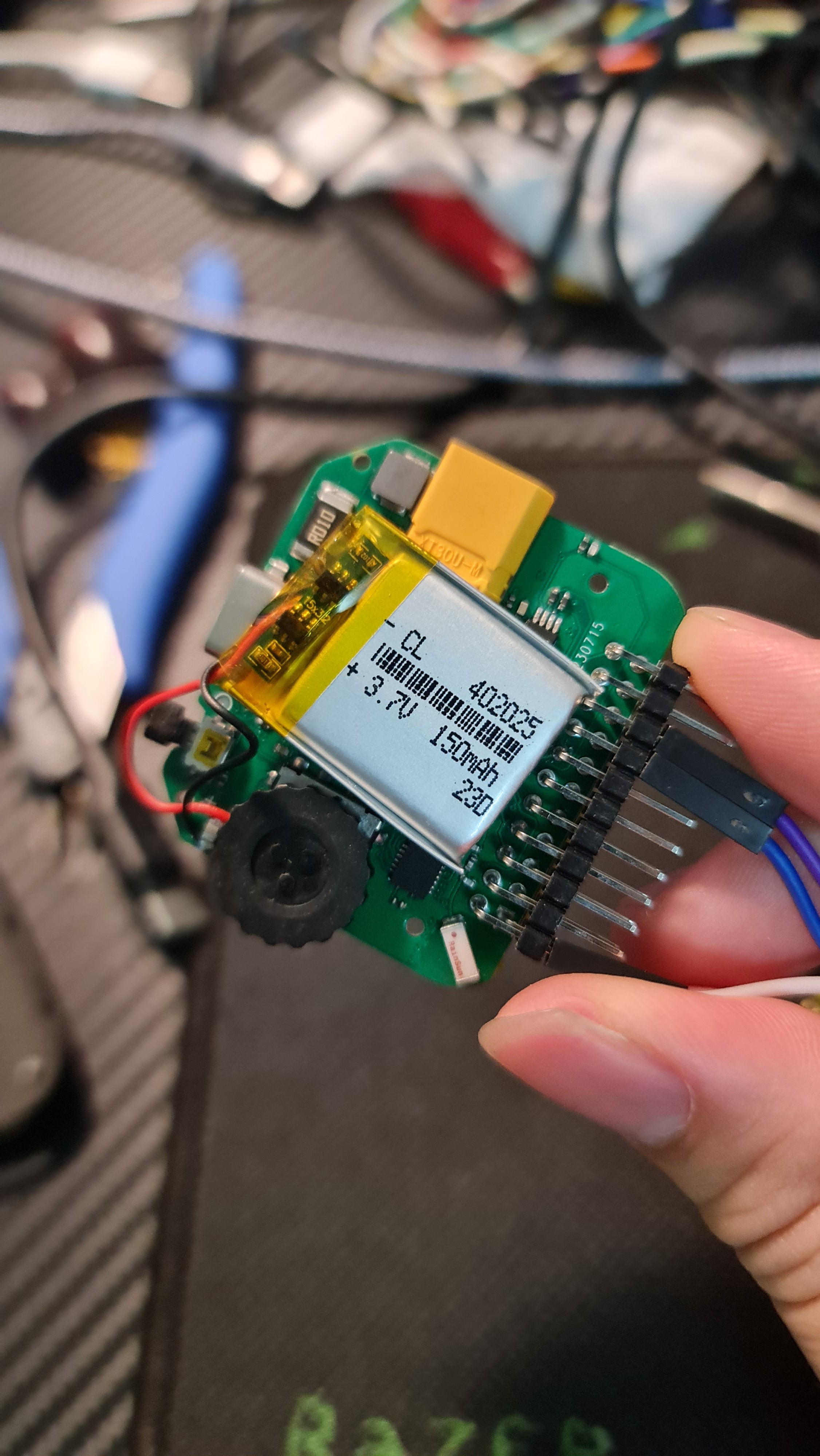
    The new casing version also allows for a doubling of the battery capacity, increasing it from 150mAh to 300mAh.

  • New hardware upgrade - PMIC

    Chu Tien Thinh (obitvn)10/22/2023 at 08:34 0 comments

    PMIC on Felini uses axp173 to support power path, battery charging, energy management, energy measurement, voltage control.
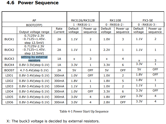
    However, the power sequence on the AXP is written OTP once on the chip at the factory, this makes it difficult for some friends who try to rebuild the felini but buy the wrong axp173 chip, this can be fixed with a few tips fishing line. However, after days of searching for a replacement IC, I found a better candidate, the RK816, with a resistor-configurable output DCDC, no matter what version the RK816 is, once powered on, The esp32 will automatically configure the default voltage to the correct voltage required by felini

    New hardware will be updated soon, after I recover from exhaustion from preparing for the hackaday prize

  • ​FELINI - Intuitive user interface

    Chu Tien Thinh (obitvn)10/10/2023 at 07:17 0 comments

    Intuitive user interface inspired by the windows phone interface on LUMIA phones. The small boxes of the interface allow users to interact easily despite the relatively small screen. Supports gestures such as swipe left, swipe right, swipe up, and down.

  • Update repo - open source project

    Chu Tien Thinh (obitvn)10/10/2023 at 03:55 0 comments

    Now, you can see the entire project resources here Hardware | Firmware Don't forget to give me a GitHub star if you find it useful ^^ .

  • Add more feature

    Chu Tien Thinh (obitvn)10/09/2023 at 15:07 0 comments

    I forgot a few ideas, and some things will take more time to perfect. That is the ability to flash offline firmware for AVR/Arduino, ESP... Infrared command learning interface, expansion breadboard... I will complete these in the near future. Of course, it wasn't in time to submit for the Hackaday prize.

  • I made a FELINI

    Chu Tien Thinh (obitvn)10/09/2023 at 15:03 0 comments

    The short video to submit for Hackaday Prize 2023 has been updated by me, you can watch it here.

  • Measure frequency

    Chu Tien Thinh (obitvn)10/03/2023 at 10:26 0 comments

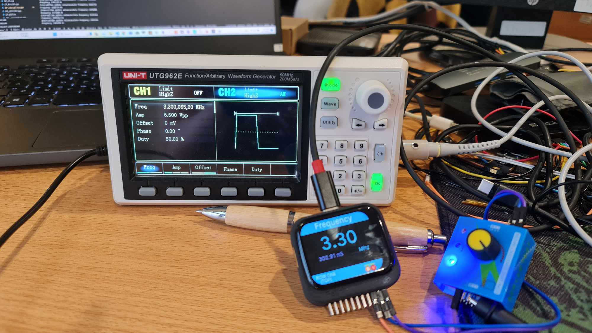
    ESP32 features a peripheral called pcnt - pulse counter, which allows counting pulses on any GPIO pin, combined with a timer. We can entirely count the number of pulses over time to calculate the frequency. And here is how I use it to measure the frequency with Felini.

  • Debug using Felini

    Chu Tien Thinh (obitvn)09/26/2023 at 06:15 0 comments

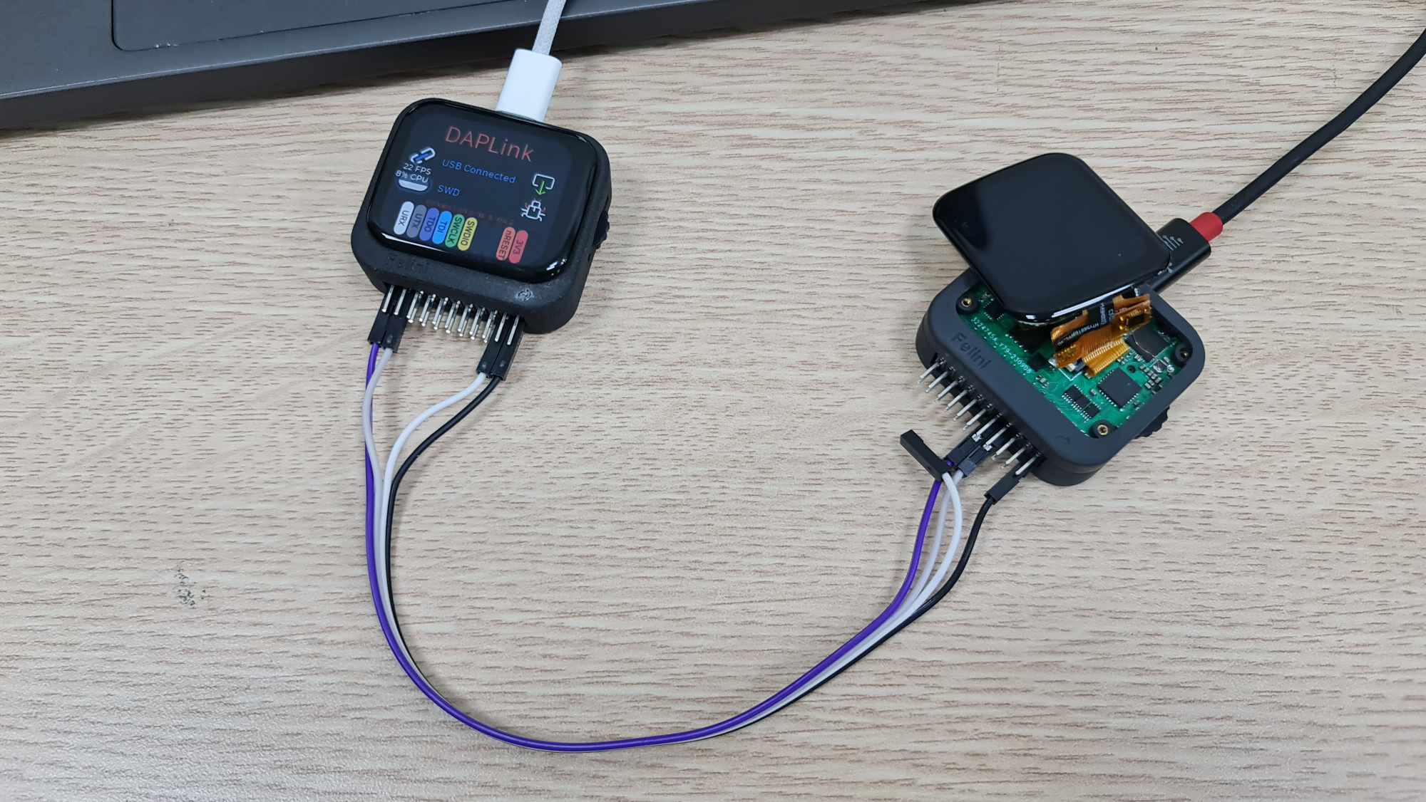
    I have an interesting picture, Felini is debugging for its sibling, Felini hardware v1.4. The new version has a small error on the axp192 pmic ic, I mistakenly bought the axp192 version without 3.3v output at dcdc1, so I need a little trick :v

  • A new hardware upgrade

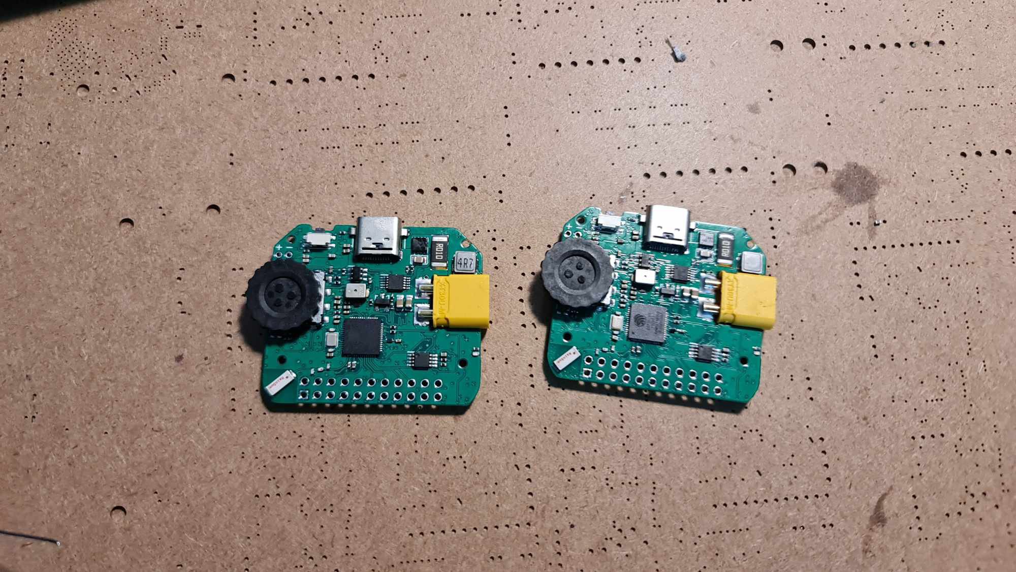
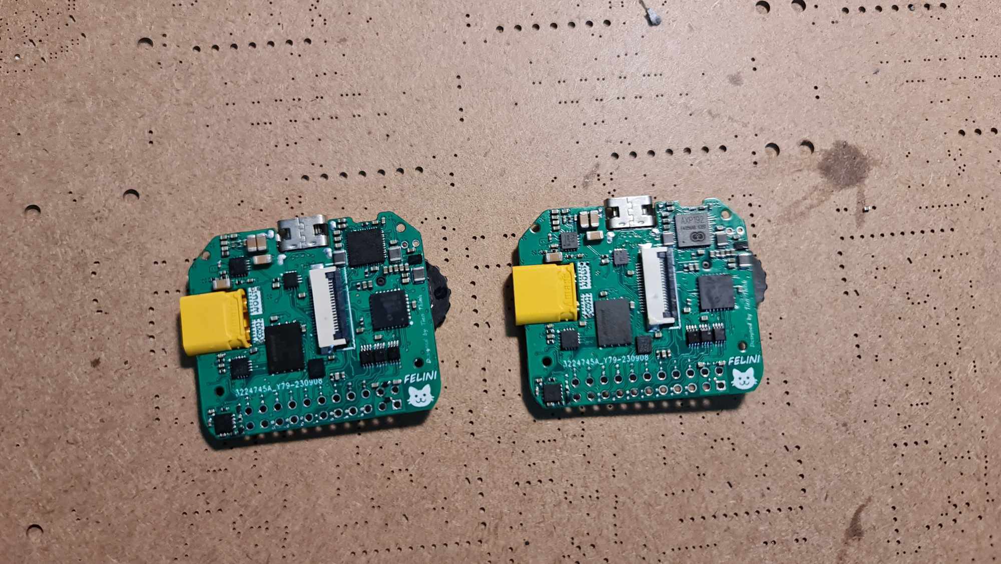
    Chu Tien Thinh (obitvn)09/26/2023 at 06:04 0 comments

    I have just completed 2 Felini boards with minor hardware modifications. By adding the TPS63811 power IC, Felini can provide customizable output voltage at the power pin within the range of 2.2-5.2V. The new design also incorporates a logic level shifting IC, in conjunction with the TPS63811, enabling Felini to easily communicate with different logic levels such as 2.8, 3.3, 4.2, and 5VDC without the need for shift level circuits.

  • UI of FELINI

    Chu Tien Thinh (obitvn)09/25/2023 at 10:14 0 comments

    Felini has a compact screen and comes with an encoder button on the side that allows users to tweak parameters easily. Therefore, a user-friendly and easy-to-operate display interface is necessary. And such an interface has appeared. It's Lumia, thanks Mr Felix Biego for the Lumia UI.

View all 17 project logs

  • 1
    Building a Felini

    The simplest, quickest, and most effective way to create your own Felini is to have the 3D casing manufactured based on the file I provide, using 3D printing with laser sintering or resin to achieve high-detail casing components. For the PCB, you should follow a similar process, outsourcing double-sided SMT assembly for the relatively straightforward device. Lastly, you just need to solder the pins onto the circuit board and assemble the components together with a bit of skill; I think it's easier than assembling LEGO. Good luck!

  • 2
    Flashing Firmware

    Felini uses esp32s3, so it can load firmware directly via USB port without the need for an external loading circuit. Please use esp-idf or esp flash tool to load the code. Normally, Felini will appear as a COM port accompanied by a USB JTAG/serial debug unit as shown below. With this status, you can load the new firmware without making any changes.


    However, when using applications related to USB ports such as DAPLink, Logic Analyzer, FELINI will automatically convert to drivers for these applications. In this case, to load the code, please exit the above applications and return to the main screen.
    In case of firmware error, the simplest way is to hold down the power button for 10 seconds to power off the device. Then turn it back on. If you still don't see the COM and USB JTAG/serial ports for loading code. Power off the device again, then hold down the middle button of the rotary encoder, at the same time, press the power button to turn on FELINI. At this time, FELINI will be in bootloader mode and ready to download new firmware. This is the boot mode mechanism through GPIO 0 of the esp32s3 (the encoder is connected to this pin). This ensures that in all cases, your FELINI cannot be bricked. Good Luck ^^

  • 3
    Case covers the device

    For the device case, you can use one of the following two printing technologies: MJF laser sintering printing (Nylon) or UV resin printing. Resin printing will give a sharper surface, but you must attach glue to the nut. For MJF, you can heat the nut submerged into the molten plastic. Personally, I like MJF better.

View all 3 instructions

Enjoy this project?

Share

Discussions

xiao_pei wrote 4 days ago point

如何首次刷新固件?

  Are you sure? yes | no

wadig88227 wrote 6 days ago point

wow good!!!

  Are you sure? yes | no

xiao_pei wrote 10/16/2024 at 14:12 point

您好作者,我是一名电子爱好者,我尝试在您的 Felini 工具 BOM 中重现 C33、L1、L2、L3 是什么,目前还没有找到

  Are you sure? yes | no

ykc1043 wrote 05/02/2024 at 17:49 point

I tried to build the latest firmware, and My Git clone project didn't have the I2C component, so I filled it out, but couldn't get it to work anyway, even in a completely new system environment. Can you give me some details of the build?

  Are you sure? yes | no

MGshawn wrote 01/10/2024 at 16:21 point

Very good project, I have tried to reproduce a version, but I face many problems. First of all, it cannot touch the screen. According to the output of the serial monitor, there should be a problem with i2c. I really have no clue. Please can you Can you give me some help?


I (0) cpu_start: App cpu up.
I (523) cpu_start: Pro cpu start user code
I (523) cpu_start: cpu freq: 240000000 Hz
I (523) cpu_start: Application information:
I (526) cpu_start: Compile time:     Jan 11 2024 00:07:11
I (532) cpu_start: ELF file SHA256:  7fc1ab1d91da012c...
I (538) cpu_start: ESP-IDF:          v5.1.1-dirty
I (544) cpu_start: Min chip rev:     v0.0
I (548) cpu_start: Max chip rev:     v0.99
I (553) cpu_start: Chip rev:         v0.2
I (558) heap_init: Initializing. RAM available for dynamic allocation:
I (565) heap_init: At 3FCA4C10 len 0002B3F0 (172 KiB): DRAM
I (572) heap_init: At 3FCD2000 len 0000E000 (56 KiB): DRAM
I (578) heap_init: At 3FCE2000 len 00007710 (29 KiB): DRAM
I (584) heap_init: At 3FCE9710 len 00005724 (21 KiB): STACK/DRAM
I (591) heap_init: At 3FCF0000 len 00008000 (32 KiB): DRAM
I (597) heap_init: At 600FE010 len 00001FD8 (7 KiB): RTCRAM
I (603) esp_psram: Adding pool of 8192K of PSRAM memory to heap allocator
I (611) spi_flash: detected chip: winbond
I (615) spi_flash: flash io: dio
I (621) sleep: Configure to isolate all GPIO pins in sleep state
I (626) sleep: Enable automatic switching of GPIO sleep configuration
I (633) app_start: Starting scheduler on CPU0
I (638) app_start: Starting scheduler on CPU1
I (638) main_task: Started on CPU0
I (648) main_task: Calling app_main()
E (652) i2c_manager: Invalid port or not configured for I2C Manager: 0
E (659) i2c_manager: Invalid port or not configured for I2C Manager: 0
W (666) RK816: rk816 id  0x30d version  0x2

E (671) i2c_manager: Invalid port or not configured for I2C Manager: 0
E (678) i2c_manager: Invalid port or not configured for I2C Manager: 0
E (686) i2c_manager: Invalid port or not configured for I2C Manager: 0
E (693) i2c_manager: Invalid port or not configured for I2C Manager: 0
E (700) i2c_manager: Invalid port or not configured for I2C Manager: 0
E (707) i2c_manager: Invalid port or not configured for I2C Manager: 0
E (714) i2c_manager: Invalid port or not configured for I2C Manager: 0
E (722) i2c_manager: Invalid port or not configured for I2C Manager: 0
E (729) i2c_manager: Invalid port or not configured for I2C Manager: 0
E (736) i2c_manager: Invalid port or not configured for I2C Manager: 0
E (743) i2c_manager: Invalid port or not configured for I2C Manager: 0
E (750) i2c_manager: Invalid port or not configured for I2C Manager: 0
E (758) i2c_manager: Invalid port or not configured for I2C Manager: 0
E (765) i2c_manager: Invalid port or not configured for I2C Manager: 0
power on source 0
I (774) RK816: dcdc1 712500, dcdc2 1500000, dcdc3 800000,
 dcdc4 800000, ldo1 800000, ldo2 800000,
 ldo3 800000, ldo4 800000, ldo5 800000, ldo6 12

E (788) i2c_manager: Invalid port or not configured for I2C Manager: 0
E (795) i2c_manager: Invalid port or not configured for I2C Manager: 0
E (803) i2c_manager: Invalid port or not configured for I2C Manager: 0
E (810) i2c_manager: Invalid port or not configured for I2C Manager: 0
E (817) i2c_manager: Invalid port or not configured for I2C Manager: 0
E (824) i2c_manager: Invalid port or not configured for I2C Manager: 0
E (831) i2c_manager: Invalid port or not configured for I2C Manager: 0
E (839) i2c_manager: Invalid port or not configured for I2C Manager: 0
E (846) ledc: ledc_set_duty(710): LEDC is not initialized
E (852) ledc: ledc_update_duty(636): LEDC is not initialized
I (1092) gpio: GPIO[3]| InputEn: 1| OutputEn: 0| OpenDrain: 0| Pullup: 1| Pulldown: 0| Intr:0
I (1093) gpio: GPIO[39]| InputEn: 1| OutputEn: 0| OpenDrain: 0| Pullup: 1| Pulldown: 0| Intr:0
I (1100) gpio: GPIO[38]| InputEn: 1| OutputEn: 0| OpenDrain: 0| Pullup: 1| Pulldown: 0| Intr:0
I (1110) gpio: GPIO[38]| InputEn: 1| OutputEn: 0| OpenDrain: 0| Pullup: 1| Pulldown: 0| Intr:0
I (1119) gpio: GPIO[39]| InputEn: 1| OutputEn: 0| OpenDrain: 0| Pullup: 1| Pulldown: 0| Intr:0
I (1328) CST816: Initializing cst816 0x15
E (1328) i2c_manager: Invalid port or not configured for I2C Manager: 0
E (1329) CST816: Error reading version from device: ERROR
E (1335) i2c_manager: Invalid port or not configured for I2C Manager: 0
E (1342) CST816: Error reading versionInfo from device: ERROR
I (1348) CST816: CST816 version 130, versionInfo: 22.145.1
E (1427) i2c_manager: Invalid port or not configured for I2C Manager: 0

  Are you sure? yes | no

Chu Tien Thinh (obitvn) wrote 01/11/2024 at 03:53 point

The new branch has some hardware changes, maybe that's the reason, you can switch back to the old-hardware branch to try again

  Are you sure? yes | no

xiao_pei wrote 4 days ago point

How did Felini flash the firmware for the first time?

  Are you sure? yes | no

South Wind wrote 10/22/2023 at 11:36 point

May I ask,Several hardware versions are expected in the future.I can't wait to experience the final version.ha

  Are you sure? yes | no

MGshawn wrote 10/19/2023 at 06:40 point

Hello author, I am an electronics enthusiast and am currently trying to copy your first version of the board. Now when I weld the power supply part, I found that the output voltage of mp28176 has reached 22v. Is this normal? Can you give me some suggestions for welding tests?  ?

  Are you sure? yes | no

Chu Tien Thinh (obitvn) wrote 10/19/2023 at 08:14 point

that's strange, the mp28167 will always output 5v because it doesn't need a feedback resistor

  Are you sure? yes | no

Chu Tien Thinh (obitvn) wrote 10/19/2023 at 08:17 point

I have soldered 5 versions and none of them have this error, what is the input voltage you give to the mp28167, usually it should be 5v when plugged in usb in normal mode, or ~20v in PD mode, in all these modes, the output of mp28167 is still 5V

  Are you sure? yes | no

MGshawn wrote 10/19/2023 at 09:30 point

It's really strange. I tested that the input voltage is indeed 5V, and after welding the power module part and turning on the power, you can hear an obvious sizzling sound of current.

  Are you sure? yes | no

MGshawn wrote 11/11/2023 at 02:02 point

The VCC pin gives about 3.6v

  Are you sure? yes | no

Chu Tien Thinh (obitvn) wrote 11/13/2023 at 06:28 point

maybe it's a problem with your axp173, i changed that ic to another pmic in the next upgrade

  Are you sure? yes | no

MGshawn wrote 12/02/2023 at 13:09 point

May I know your soldering test sequence?

  Are you sure? yes | no

pnewb wrote 10/11/2023 at 22:45 point

Would it be possible to get a Pick N Place export from Altium?  I tried converting importing to the tools available to me so I could generate it, and didn't have any luck there.  The gerbers and BOM are wonderful, but without the PNP file it's difficult to get them assembled.

  Are you sure? yes | no

Chu Tien Thinh (obitvn) wrote 10/12/2023 at 01:59 point

I want to upgrade the hardware to add the RLC measurement feature to Felini. Hackadayprize's progress is so urgent that I can't update it in time to submit. Please wait for me to update the new hardware first.

  Are you sure? yes | no

pnewb wrote 10/12/2023 at 03:10 point

Completely understand.  Happy to wait until you’re ready and exited to build a few to give to some friends as gifts!

  Are you sure? yes | no

zyndram wrote 09/10/2023 at 14:25 point

How plug in Irda?

How plug in soundmodem (look at android program rattlegram or waver) and send data trought walkie talkie.

How plug diode/flashlight and send data aplabeth morsa and meybe camera to receive it.

How create a mesh network using BT or CC1101 (433MHz or 868MHz)

  Are you sure? yes | no

Chu Tien Thinh (obitvn) wrote 10/10/2023 at 03:57 point

It will appear in future versions, in the first prototype I aim for a proof of concept (PoC) and focus on developing common features first, then, useful features Other benefits will also be added, it's technically feasible, so it just takes more time to complete it.

  Are you sure? yes | no

Index303 wrote 09/09/2023 at 12:24 point

Very good idea and design!  I can't wait to make one "felini", will the source code be open source?

  Are you sure? yes | no

Chu Tien Thinh (obitvn) wrote 09/17/2023 at 09:37 point

Certainly.

  Are you sure? yes | no

Chu Tien Thinh (obitvn) wrote 10/10/2023 at 03:57 point

now, it's opensource

  Are you sure? yes | no

Kevincoooool wrote 09/04/2023 at 08:34 point

Hi ,Hello, how is the firmware development progress now

  Are you sure? yes | no

Chu Tien Thinh (obitvn) wrote 09/17/2023 at 09:56 point

https://space.bilibili.com/59041601 video channel is yours, right? You have very impressive projects

  Are you sure? yes | no

Kevincoooool wrote 09/25/2023 at 07:54 point

Haha ,yes that's me.I'm also making a tool like this project

  Are you sure? yes | no

Paul McClay wrote 08/21/2023 at 00:55 point

Random idea: to make it useful in a breadboard, can you arrange pin assignments for the 2*11 header so that it's at least harmless to short across the 11 pin pairs? And distribute 11 useful pin functions along the header? Basic stuff like power (in or out), ADC, and whatever else fits. So that if stuffed into a breadboard it would a) not break, and b) do whatever functions you get to fit in 11 pins.

  Are you sure? yes | no

Chu Tien Thinh (obitvn) wrote 08/21/2023 at 01:53 point

Thank you, I've been considering this since the idea, for use with breadboards it's better to have an adapter to get the most out of the feature. Felini can also be plugged directly into the breadboard because the pins in its two rows are not used at the same time.

  Are you sure? yes | no

david wrote 08/14/2023 at 20:07 point

I'd be worried about bending the pins on the male header. How about changing it to a female header? You could use a male-to-male header if you needed the male pins.

  Are you sure? yes | no

Chu Tien Thinh (obitvn) wrote 08/15/2023 at 01:39 point

yes, it's personal preference, replacing to the female header is simple

  Are you sure? yes | no

Prashanth Kumar wrote 08/09/2023 at 06:39 point

It would be good if you can make the software open source, so more people can contribute to it

  Are you sure? yes | no

Chu Tien Thinh (obitvn) wrote 08/10/2023 at 03:16 point

thanks, it will definitely be open source, but I need some time to clean up code and prepare before people can contribute to it

  Are you sure? yes | no

Prashanth Kumar wrote 08/09/2023 at 06:36 point

If you are willing to sell pre-assembled boards, please let me know

  Are you sure? yes | no

Xieshi Zhang wrote 08/06/2023 at 01:02 point

Wow! Such an elegant and innovative solution to a common problem. I definitely need this.

  Are you sure? yes | no

cheyen.s21 wrote 08/05/2023 at 13:31 point

Hey, would this be able to run or test usb otg connected webcams? Hoping it can test and display a usb webcam

  Are you sure? yes | no

Chu Tien Thinh (obitvn) wrote 08/05/2023 at 15:37 point

yes it is a good idea, i will look into it in the future when the software is stable, thanks you

  Are you sure? yes | no

cheyen.s21 wrote 08/05/2023 at 20:50 point

You're welcome, i've actually been on a quest for this such item for a very long time TBH and came across your post a few days ago and saved it at work. Would be amazing to see if this will be the all in one capable gadget. They are very low resolution for now  ( incase data rate is an issue or limited ) ( 256*192 25fps and 256*192 50fps no native MJPEG output though (but i guess the raw data can be converted or viewed raw? 

  Are you sure? yes | no

Paul McClay wrote 08/04/2023 at 01:29 point

This sounds like a great "Gearing Up" project! 

As a power supply, does it trigger USB-C PD for high voltage & current?

  Are you sure? yes | no

Chu Tien Thinh (obitvn) wrote 08/04/2023 at 02:31 point

In theory, it will support USB-PD and PPS to customize the desired voltage level, which will be output through the XT30-M port on the left side of the device. Currently, I am dedicating time to finalize this feature and many others.

  Are you sure? yes | no

Paul McClay wrote 08/04/2023 at 17:30 point

Yes PPS is more correctly what I was thinking of. Liking the idea.

  Are you sure? yes | no

Similar Projects

Does this project spark your interest?

Become a member to follow this project and never miss any updates