Overview
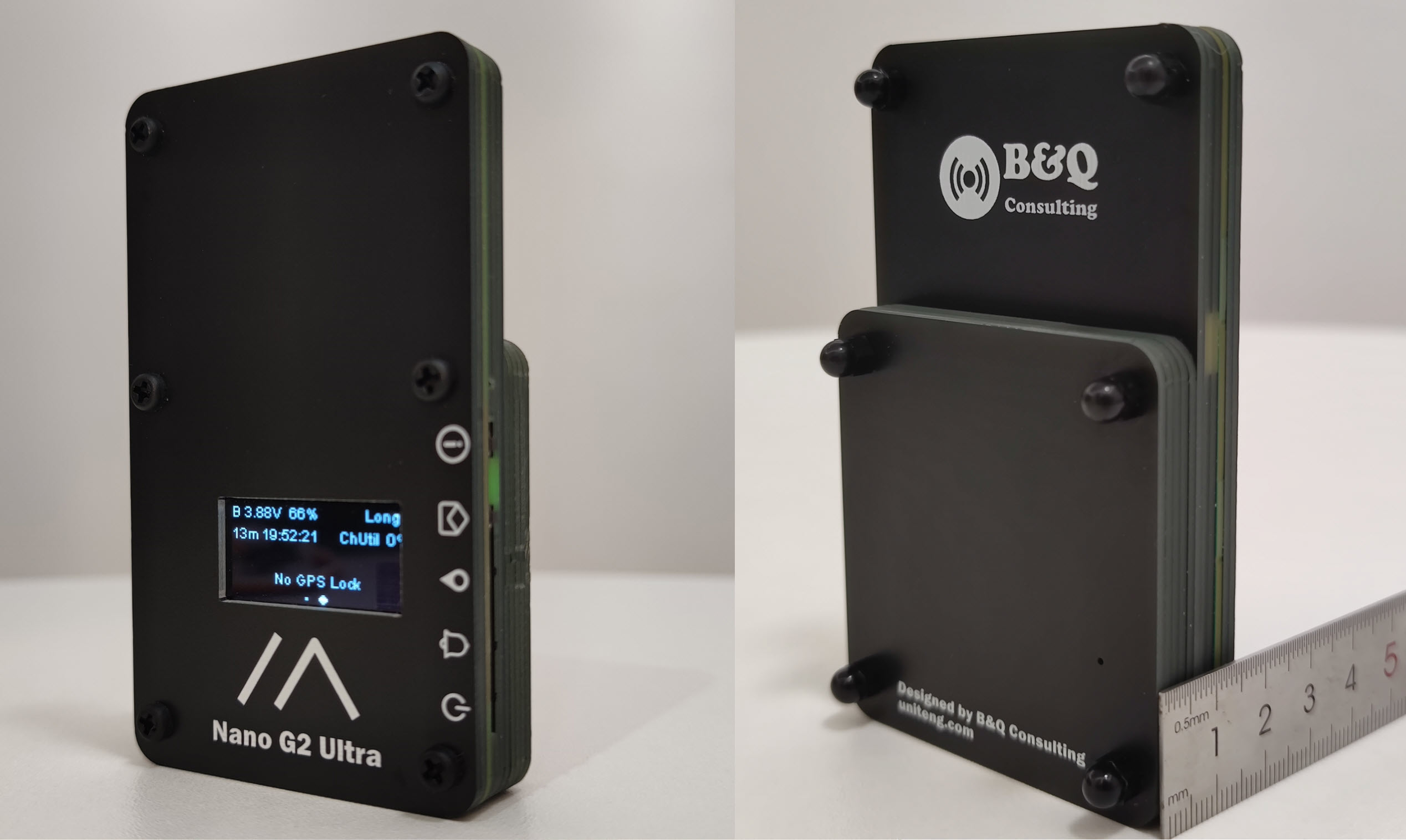
The Nano Series devices are engineered to be a portable and durable solution for outdoor adventures such as hiking, piloting, skiing and more. They are designed to strike a balance between RF performance, size, ruggedness, and power efficiency, providing users with a reliable solution in various outdoor environments.
For the firmware, all Nano Series devices come with pre-installed Meshtastic. More detials could be found in the The Latest Firmware section.
The primary design goal of the Meshtastic[2] Mesh Device Nano G2 Ultra is to reduce power consumption and improve battery life by using the low power MCU NRF52840 and optimizing the power relatived designs. The typical battery life is optimized to be about 3.5 days. Nano G2 Ultra and Nano G1 Explorer have exactly the same Lora front-end circuit design and internal wideband Lora antenna, which supports frequencies from 815 Mhz to 940 Mhz. The wideband antenna, combined with an optimized wideband Lora RF frontend circuit, enables the Nano G2 Ultra to work with the majority of regions' LoRa frequency bands around the world without the need for antenna changes. The design of the Nano G2 Ultra also takes into account the potential effect of the human body on its antenna performance, ensuring optimal RF performance even when carried in a pocket.
Power Consumption and Features Comparison of Nano G2 Ultra and Nano G1 Explorer
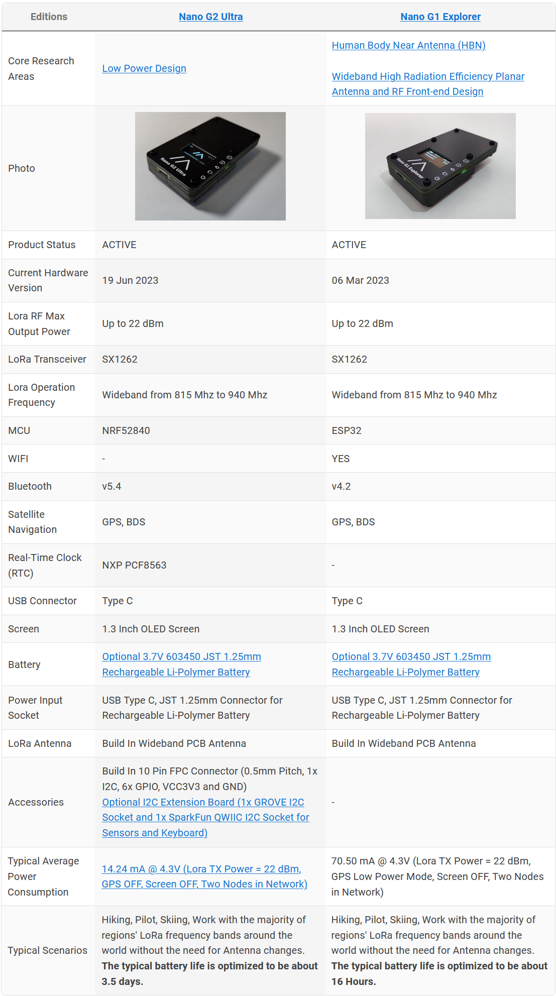
In general, Nano G2 Ultra is not designed to replace Nano G1 Explorer, Nano G2 Ultra focuses on low power, and Nano G1 Explorer supports WIFI.
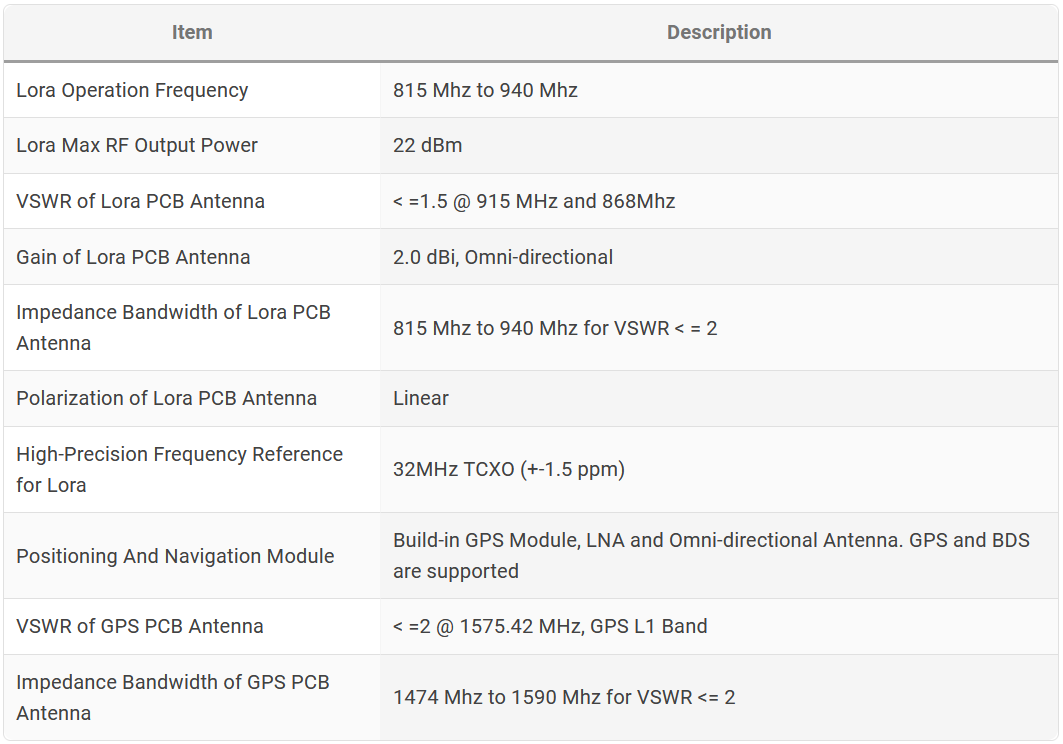
Typical RF Performance:
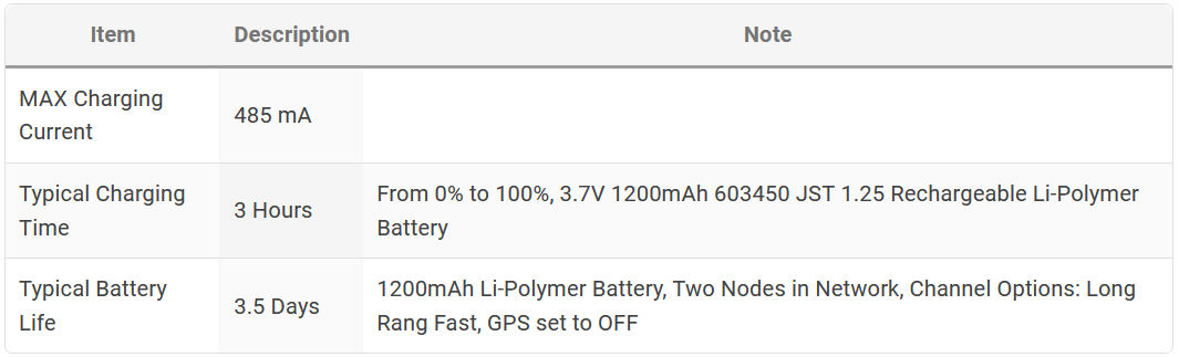
Electrical Characteristics:
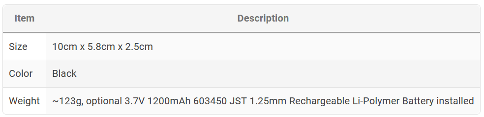
Dimension:
Hardware
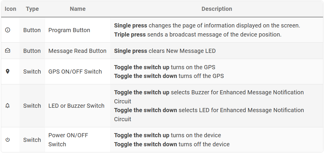
Switch/Button Definition
PCB
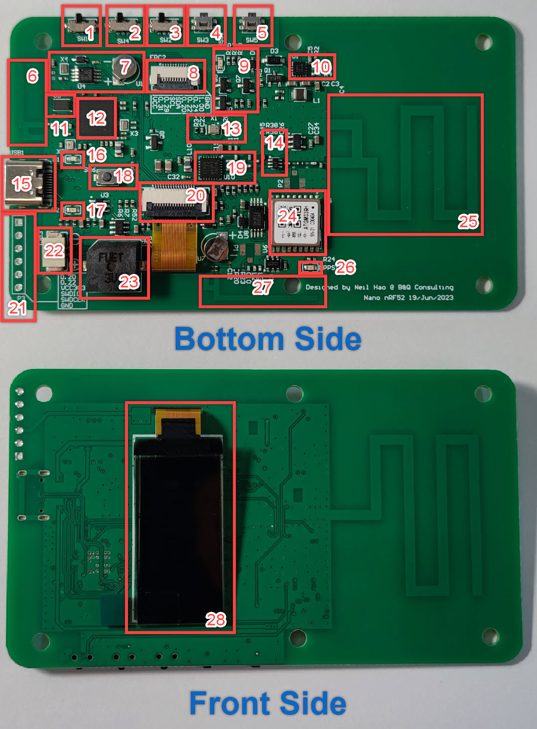
- Power ON/OFF Switch
- LED or Buzzer Switch for Enhanced Message Notification Circuit
- GPS ON/OFF Switch
- Message Read Button - Clear New Message LED
- User Button
- Internal Bluetooth Antenna
- Real-Time Clock (RTC), Part No. NXP PCF8563
- 10 Pin FPC Connector (0.5mm Pitch, 1x I2C, 6x GPIO, VCC3V3 and GND)
- Enhanced Message Notification Circuit and New Message LED Indicator (Green)
- Buck-boost converter, > 95% efficiency, Texas Instruments(TI) TPS63051
- Quad SPI 16Mbit Flash
- nRF52840 - Multiprotocol Bluetooth 5.4 SoC
- 32MHz TCXO (+-1.5 ppm), Part No. 1XXD32000MBA from DAISHINKU CORP. (KDS)
- RF Switch
- USB Type C Socket
- Battery Charging LED Indicator (Red)
- Battery Standby LED Indicator (Green)
- Reset Button for nRF52840
- Semtech SX1262 Lora Transceiver
- FPC Connector for OLED Screen
- Serial Wire Debug (SWD) Port for nRF52840
- JST 1.25mm Connector for optional 3.7V 603450 Rechargeable Li-Polymer Battery
- Active Buzzer
- ATGM336H-5N Whole Constellation Positioning and Navigation Module
- Internal Wideband Lora Antenna
- GPS Pulse Per Second (PPS) LED Indicator, the PPS LED is functional if and only if the board is powered by the external power. (Improving the battery life)
- GPS Omni-directional Antenna
- 1.3 Inch OLED Screen
Mechanical Design
Similar as Nano G1 Explorer, the Nano G2 Ultra is also constructed by stacking up PCB boards.This method offers a good balance of cost and mechanical strength. An optional 3.7V 603450 JST 1.25mm Rechargeable Li-Polymer Battery could be installed.

Note: Blue Rectangle - Nylon Machine Screws and Nuts
Power Consumption Measurement
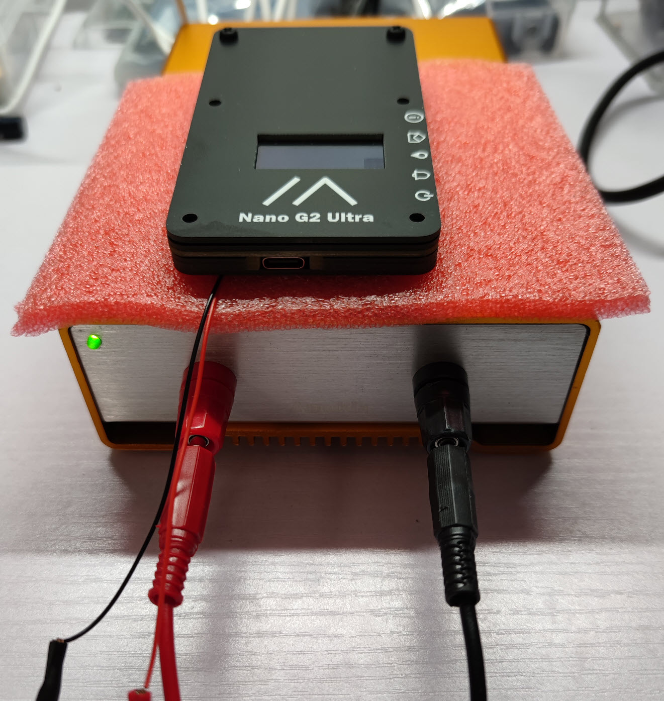
Instrument Setup
To test the power consumption when powered by battery, connect the Micro Power Analyzer to the Nano G2 Ultra's JST 1.25mm Connector for optional 3.7V 603450 Rechargeable Li-Polymer Battery. The power supply voltage is set to 4.3V.
The following items will be measured:
- Average Power Consumption
- Power Consumption when GPS OFF a. Lora TX mode, GPS OFF, Screen OFF b. Lora RX mode, GPS OFF, Screen OFF c. Lora RX mode, GPS OFF, Screen ON
- Power Consumption when GPS ON e. Lora TX mode, GPS ON, Screen OFF f. Lora RX mode, GPS ON, Screen OFF
Measurements
- Average Power Consumption
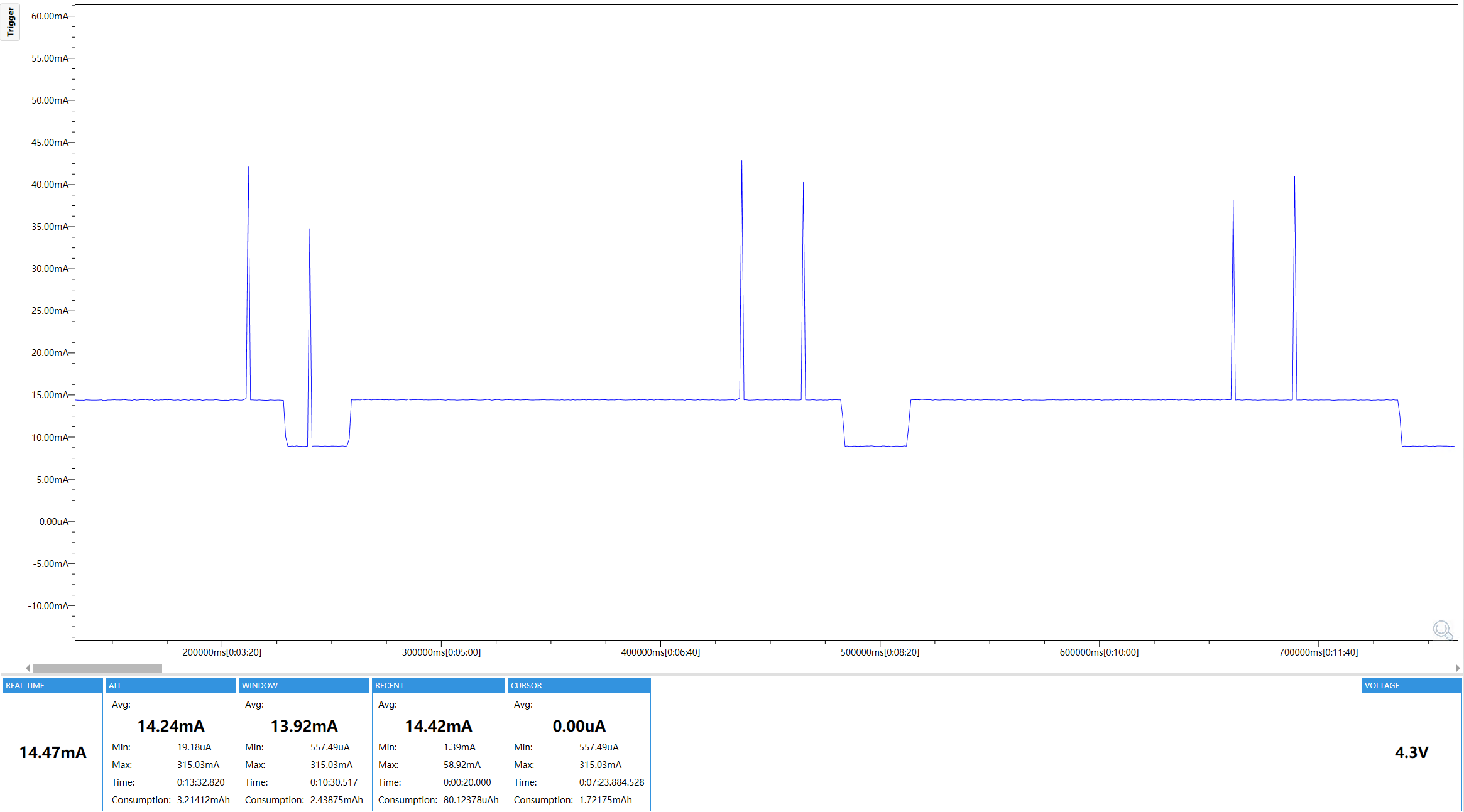
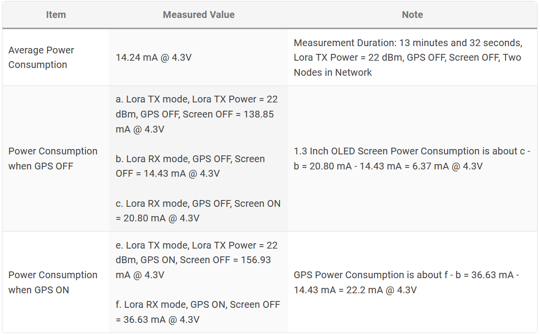
![nano_g2_ultra_average_power_consumption.png]() Average Power Consumption = 14.24 mA @ 4.3V, Measurement Duration: 13 minutes and 32 seconds, Lora TX Power = 22 dBm, GPS OFF, Screen OFF, Two Nodes in Network According to the figure above, Meshtastic Firmware sometimes enters the sleep mode to further reduce power consumption. With the continuous optimization of the firmware, it can be expected that the sleep time will be longer and the power consumption will be further reduced.
Average Power Consumption = 14.24 mA @ 4.3V, Measurement Duration: 13 minutes and 32 seconds, Lora TX Power = 22 dBm, GPS OFF, Screen OFF, Two Nodes in Network According to the figure above, Meshtastic Firmware sometimes enters the sleep mode to further reduce power consumption. With the continuous optimization of the firmware, it can be expected that the sleep time will be longer and the power consumption will be further reduced. - Power Consumption when GPS OFF
![nano_g2_ultra_power_consumption_when_gps_off.png]() a. Lora TX mode, Lora TX Power = 22 dBm, GPS OFF, Screen OFF = 138.85 mA @ 4.3V
b. Lora RX mode, GPS OFF, Screen OFF = 14.43 mA @ 4.3V
c. Lora RX mode, GPS OFF, Screen ON = 20.80 mA @ 4.3V
From the above data, we know that the power consumption of the screen is about c - b = 20.80 mA - 14.43 mA = 6.37 mA @ 4.3V
a. Lora TX mode, Lora TX Power = 22 dBm, GPS OFF, Screen OFF = 138.85 mA @ 4.3V
b. Lora RX mode, GPS OFF, Screen OFF = 14.43 mA @ 4.3V
c. Lora RX mode, GPS OFF, Screen ON = 20.80 mA @ 4.3V
From the above data, we know that the power consumption of the screen is about c - b = 20.80 mA - 14.43 mA = 6.37 mA @ 4.3V - Power Consumption when GPS ON
![nano_g2_ultra_power_consumption_when_gps_on.png]() e. Lora TX mode, Lora TX Power = 22 dBm, GPS ON, Screen OFF = 156.93 mA @ 4.3V
f. Lora RX mode, GPS ON, Screen OFF = 36.63 mA @ 4.3V
From the above data, we know that the power consumption of the GPS is about f - b = 36.63 mA - 14.43 mA = 22.2 mA @ 4.3V
e. Lora TX mode, Lora TX Power = 22 dBm, GPS ON, Screen OFF = 156.93 mA @ 4.3V
f. Lora RX mode, GPS ON, Screen OFF = 36.63 mA @ 4.3V
From the above data, we know that the power consumption of the GPS is about f - b = 36.63 mA - 14.43 mA = 22.2 mA @ 4.3V
 Average Power Consumption = 14.24 mA @ 4.3V, Measurement Duration: 13 minutes and 32 seconds, Lora TX Power = 22 dBm, GPS OFF, Screen OFF, Two Nodes in Network According to the figure above, Meshtastic Firmware sometimes enters the sleep mode to further reduce power consumption. With the continuous optimization of the firmware, it can be expected that the sleep time will be longer and the power consumption will be further reduced.
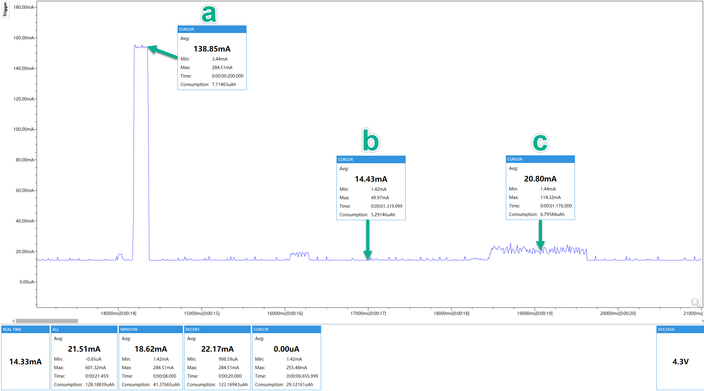 a. Lora TX mode, Lora TX Power = 22 dBm, GPS OFF, Screen OFF = 138.85 mA @ 4.3V
b. Lora RX mode, GPS OFF, Screen OFF = 14.43 mA @ 4.3V
c. Lora RX mode, GPS OFF, Screen ON = 20.80 mA @ 4.3V
From the above data, we know that the power consumption of the screen is about c - b = 20.80 mA - 14.43 mA = 6.37 mA @ 4.3V
a. Lora TX mode, Lora TX Power = 22 dBm, GPS OFF, Screen OFF = 138.85 mA @ 4.3V
b. Lora RX mode, GPS OFF, Screen OFF = 14.43 mA @ 4.3V
c. Lora RX mode, GPS OFF, Screen ON = 20.80 mA @ 4.3V
From the above data, we know that the power consumption of the screen is about c - b = 20.80 mA - 14.43 mA = 6.37 mA @ 4.3V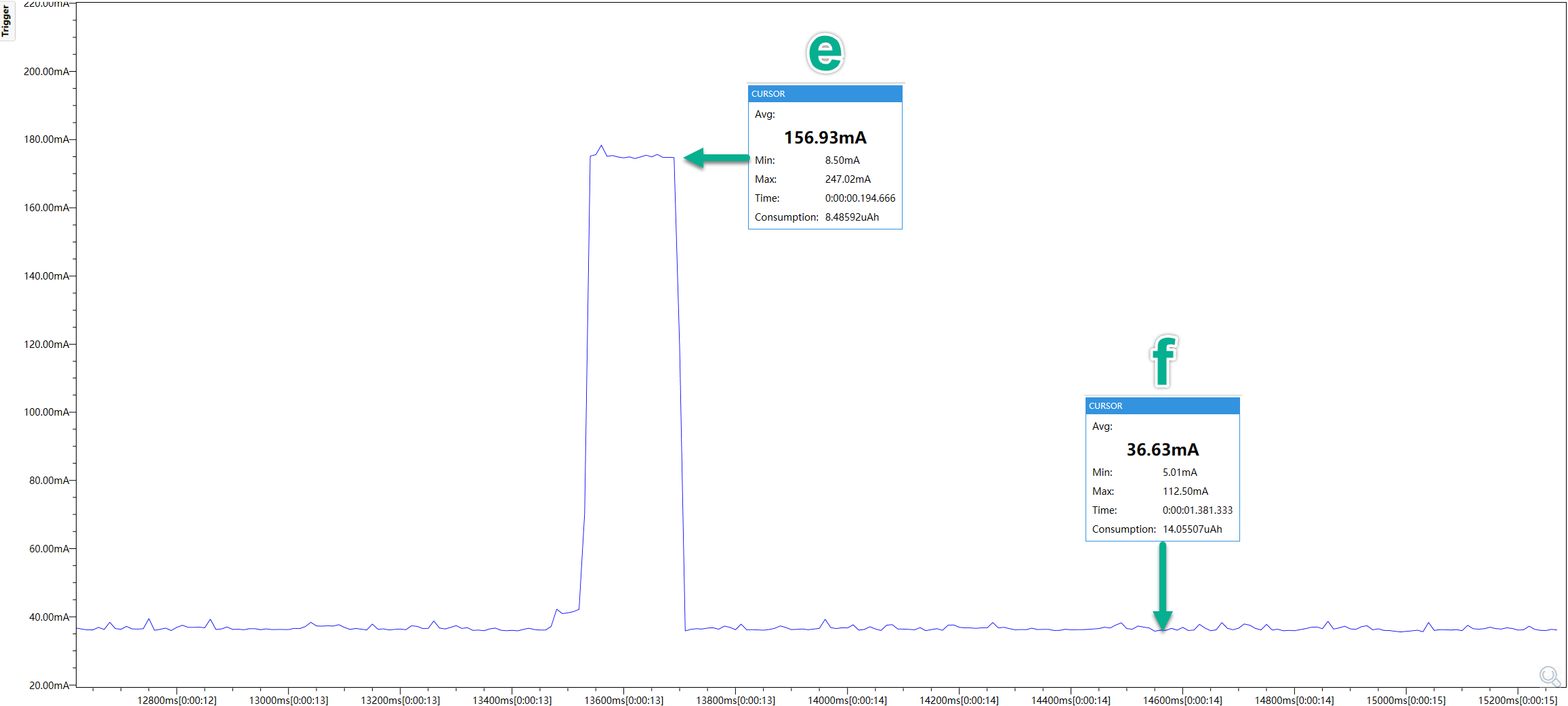 e. Lora TX mode, Lora TX Power = 22 dBm, GPS ON, Screen OFF = 156.93 mA @ 4.3V
f. Lora RX mode, GPS ON, Screen OFF = 36.63 mA @ 4.3V
From the above data, we know that the power consumption of the GPS is about f - b = 36.63 mA - 14.43 mA = 22.2 mA @ 4.3V
e. Lora TX mode, Lora TX Power = 22 dBm, GPS ON, Screen OFF = 156.93 mA @ 4.3V
f. Lora RX mode, GPS ON, Screen OFF = 36.63 mA @ 4.3V
From the above data, we know that the power consumption of the GPS is about f - b = 36.63 mA - 14.43 mA = 22.2 mA @ 4.3VSummary for Power Consumption Measurement
RF Design - Lora
Nano G2 Ultra and Nano G1 Explorer have exactly the same Lora front-end circuit design and internal wideband Lora antenna. For detailed test information, please refer to the WIKI page of Nano G1 Explorer.
RF Design - GPS
Nano G2 Ultra and Nano G1 Explorer have exactly the same GPS front-end circuit design and internal GPS antenna. For detailed test information, please refer to the WIKI page of Nano G1 Explorer.
The Latest Firmware
Drag & Drop nRF52 Firmware Updates
Before entering bootloader mode, please Toggle the LED or Buzzer Switch down to select LED for Enhanced Message Notification Circuit. Otherwise, the buzzer will make noise because the bootloader will set all GPIOs to input mode.
Download and unzip the latest firmware from Meshtastic Downloads.
- Connect your device to your computer with a USB data cable.
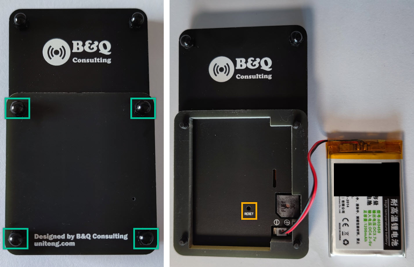
- Double click the Reset Button on your device (this will put it into bootloader mode)
![firmware_updates_step2.jpg]() Remove the nylon nuts located within the four green rectangles and take off the battery cover. Reset Button (Yellow Rectangle) is under the battery, please use a ballpoint pen or SIM Needle to click the Reset Button.
Remove the nylon nuts located within the four green rectangles and take off the battery cover. Reset Button (Yellow Rectangle) is under the battery, please use a ballpoint pen or SIM Needle to click the Reset Button. - Notice a new drive will be mounted on your computer (Windows, Mac, or Linux)
![firmware_updates_step3.jpg]()
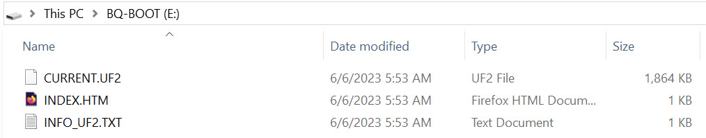
- Open this drive and you should see three files: CURRENT.UF2, INDEX.HTM, and INFO_UF2.TXT
![firmware_updates_step4.jpg]()
- Drop the appropriate firmware file (firmware-nano-g2-ultra-vx.x.x-xxxxxxx.uf2) from the release onto this drive.
![firmware_updates_step5.jpg]()
 Remove the nylon nuts located within the four green rectangles and take off the battery cover. Reset Button (Yellow Rectangle) is under the battery, please use a ballpoint pen or SIM Needle to click the Reset Button.
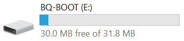
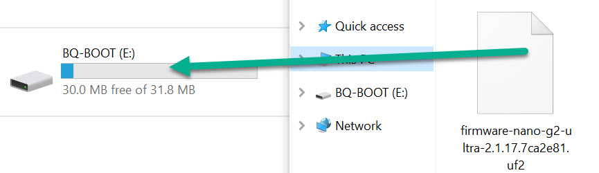
Once the file has finished copying onto the drive, the device will reboot and install the Meshtastic firmware.
Previous versions of the Meshtastic firmware may save stale data, causing devices to get stuck in a crash loop during startup. If you experience issues when upgrading your nRF52 device from a previous version of Meshtastic, you may need to perform a full factory reset of the internal flash memory. Follow the guide to factory erase your nRF52 device before continuing to flash firmware.
More Information: https://meshtastic.org/docs/getting-started/flashing-firmware/nrf52/drag-n-drop
Software
Android
The Android APP could be downloaded and installed from the Google Play Store: https://play.google.com/store/apps/details?id=com.geeksville.mesh
APP Source Code: https://github.com/meshtastic/Meshtastic-Android/releases
iOS
The iOS APP could be downloaded and installed from following URL: https://meshtastic.org/docs/category/apple-apps
Python / MQTT and More
Python, Web Interface and MQTT are also supported by the Meshtastic. More information: https://meshtastic.org/docs/software
Advanced Topics
Accessories
GPIO access is fundamentally dangerous because invalid options can physically damage or destroy your hardware. Ensure that you fully understand the schematic for your particular device before trying this.
Nano G2 Ultra has a 10 Pin FPC Connector (0.5mm Pitch), this Connector contains an I2C interface, 6 GPIO, VCC (3.3VDC) and GND. This connector can be used to support accessory designs.
Optional I2C Extension Board
The I2C Extension Board has two I2C sockets, which are used to connect GROVE[3], Adafruit STEMMA QT[4] and SparkFun QWIIC[5] devices. These two I2C sockets are based on the 10 Pin FPC Connector of Nano G2 Ultra. 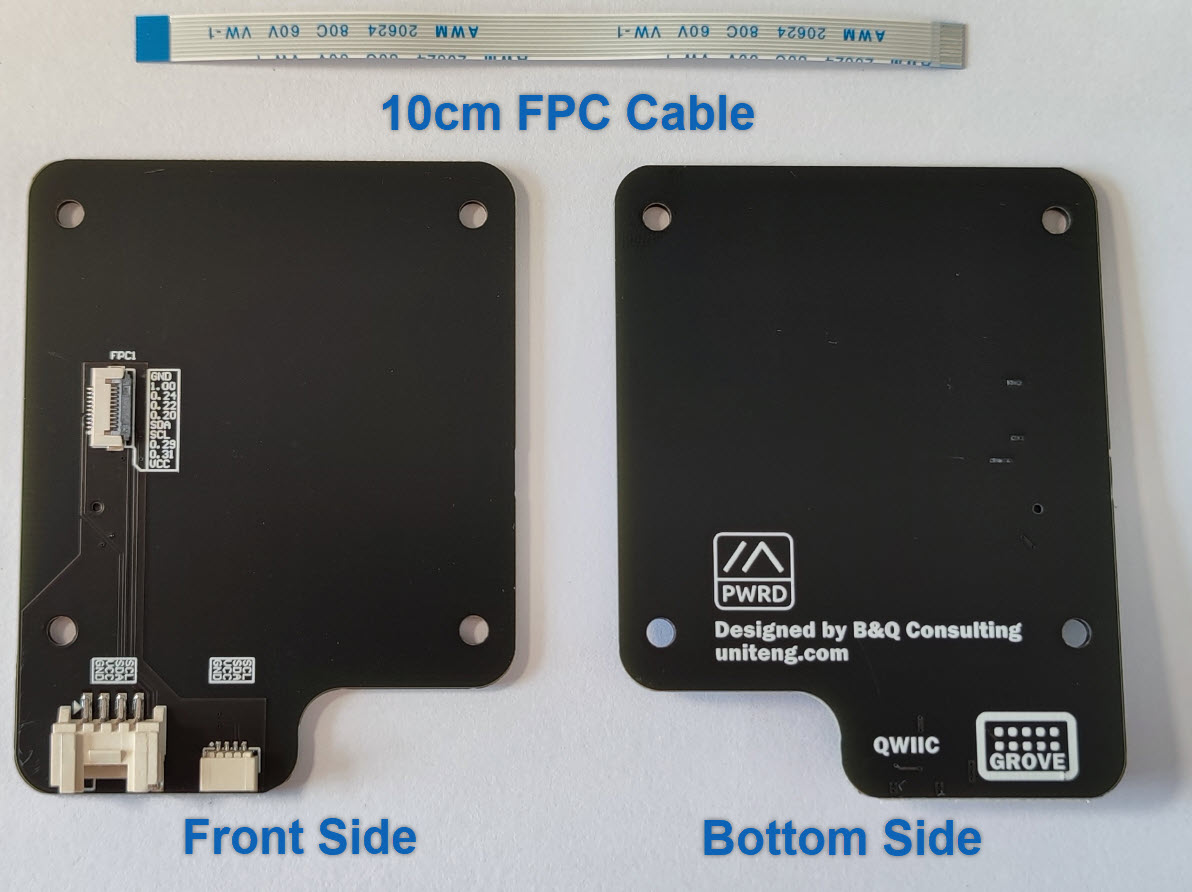
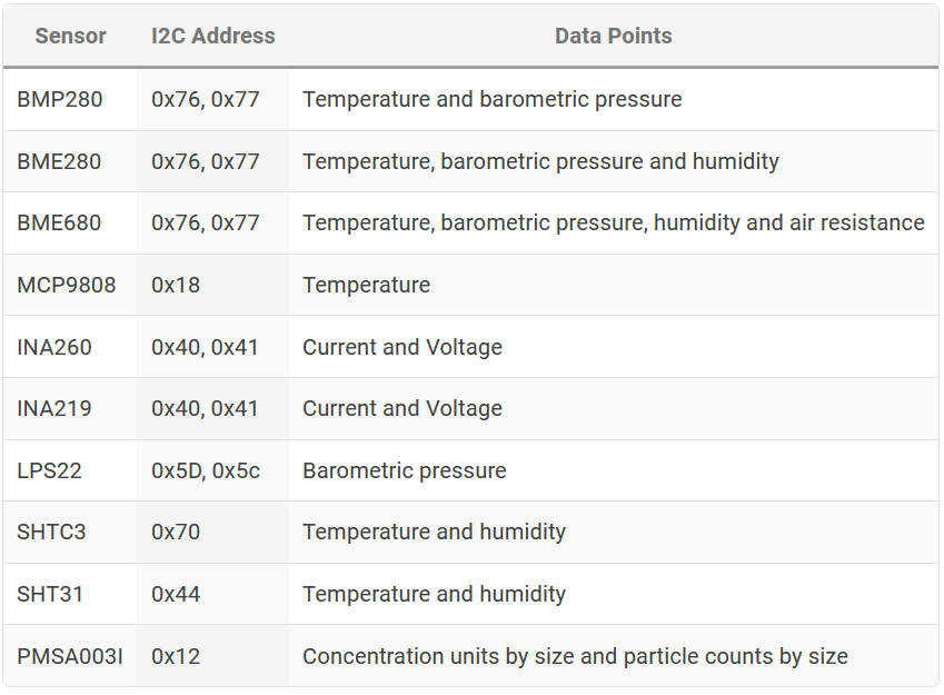
Meshtastic supported I2C devices
Telemetry Module
Supported sensors connected to the I2C bus of the device will be automatically detected at startup. Environment Telemetry and Air Quality must be enabled for them to be instrumented and their readings sent over the mesh.
More Information: https://meshtastic.org/docs/settings/moduleconfig/telemetry
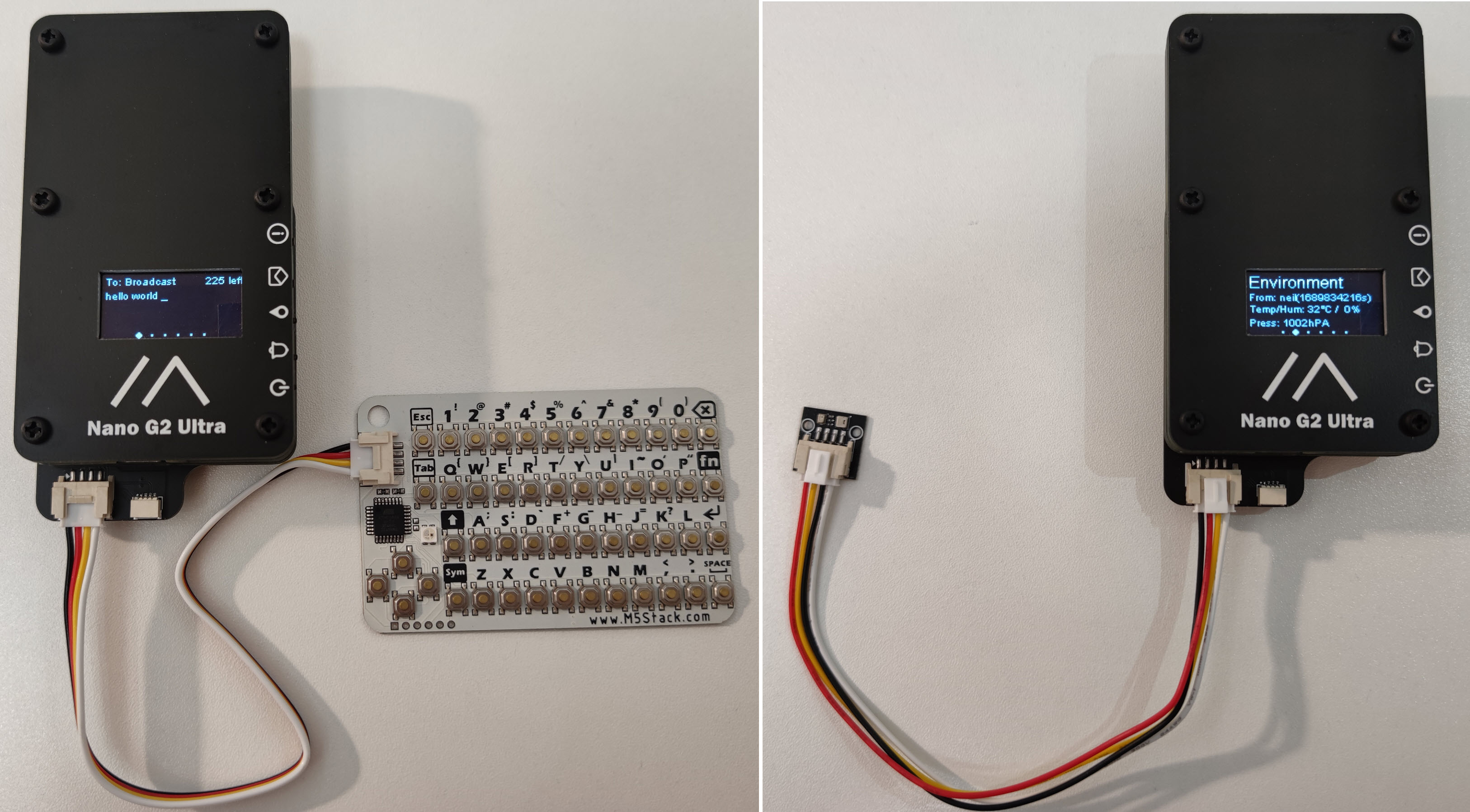
Canned Message Module
Canned Message Module, I2C Extension Board and M5Stack CardKB[6] can turn Nano G2 Ultra into a stand-alone device, which can send and receive messages without a mobile phone.
- M5Stack CardKB The CardKB is fully supported in freetext mode and select mode. Use UP/DOWN/ENTER to select a predefined message and send it. For a freetext message, just type it in and press ENTER to send it. If you don't want to broadcast your freetext message, you can use the CardKB to send it to a specific node. Just press TAB and select the target node with the LEFT/RIGHT keys. The message will be sent to the node with the matching name and node number. The target node will be remembered for your next message.
More Information: https://meshtastic.org/docs/settings/moduleconfig/canned-message#cardkb
Installation Instructions
Nano G2 Ultra and I2C Extension Board are connected by 10 Pin FPC Connectors (0.5mm Pitch, Front Flip-Lock Actuator) and a 10cm FPC cable. The figure below explains in detail about how to operate the FPC Connector. 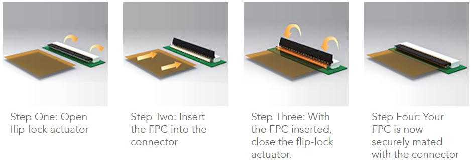
- To install the I2C expansion board, you need to remove the nylon nuts located inside the six green rectangles, then remove the six boards until you can see the green main board.
![i2c_expansion_board_step1.jpg]()
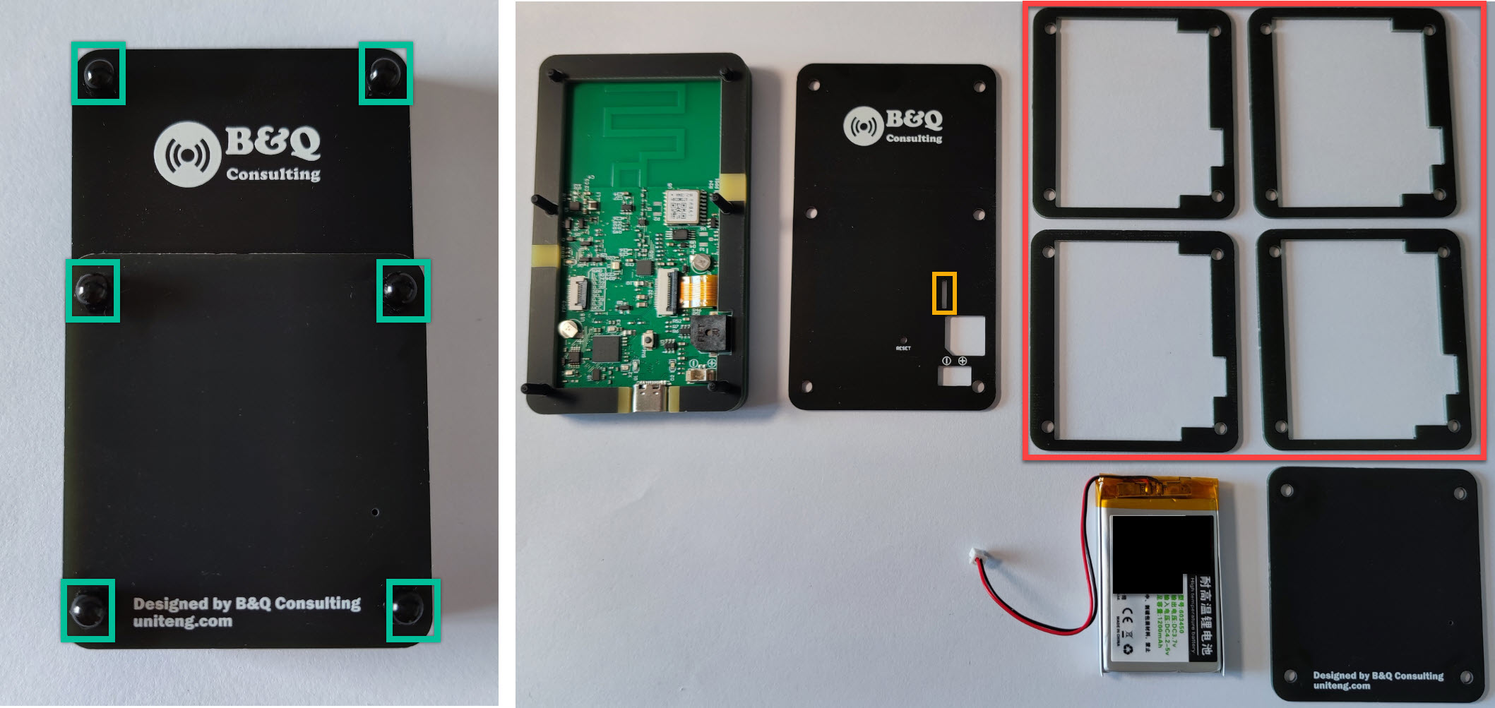
Before removing the sixth board, disconnect the battery. Be sure to disconnect the battery and USB cable to ensure the following operations will not damage the device.
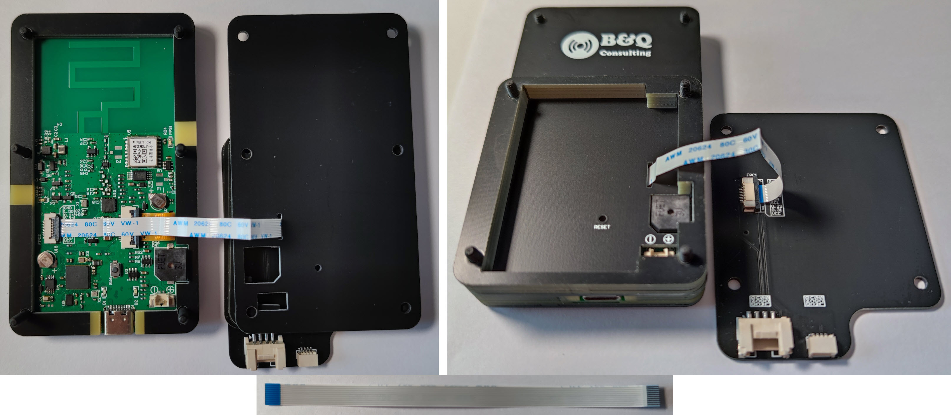
- Use a 10cm FPC cable to connect the 10 Pin FPC Connector (FPC2) on the green motherboard. Pass through the hole in the yellow rectangle and the four boards in the red rectangle in Step 1. Finally, connect the 10cm FPC cable to the 10 Pin FPC Connector (FPC1) on the I2C Extension Board. When connecting the 10cm FPC cable to connect the 10 Pin FPC Connector, always keep the blue plastic piece on the 10cm FPC cable facing towards you.
![i2c_expansion_board_step2.jpg]()
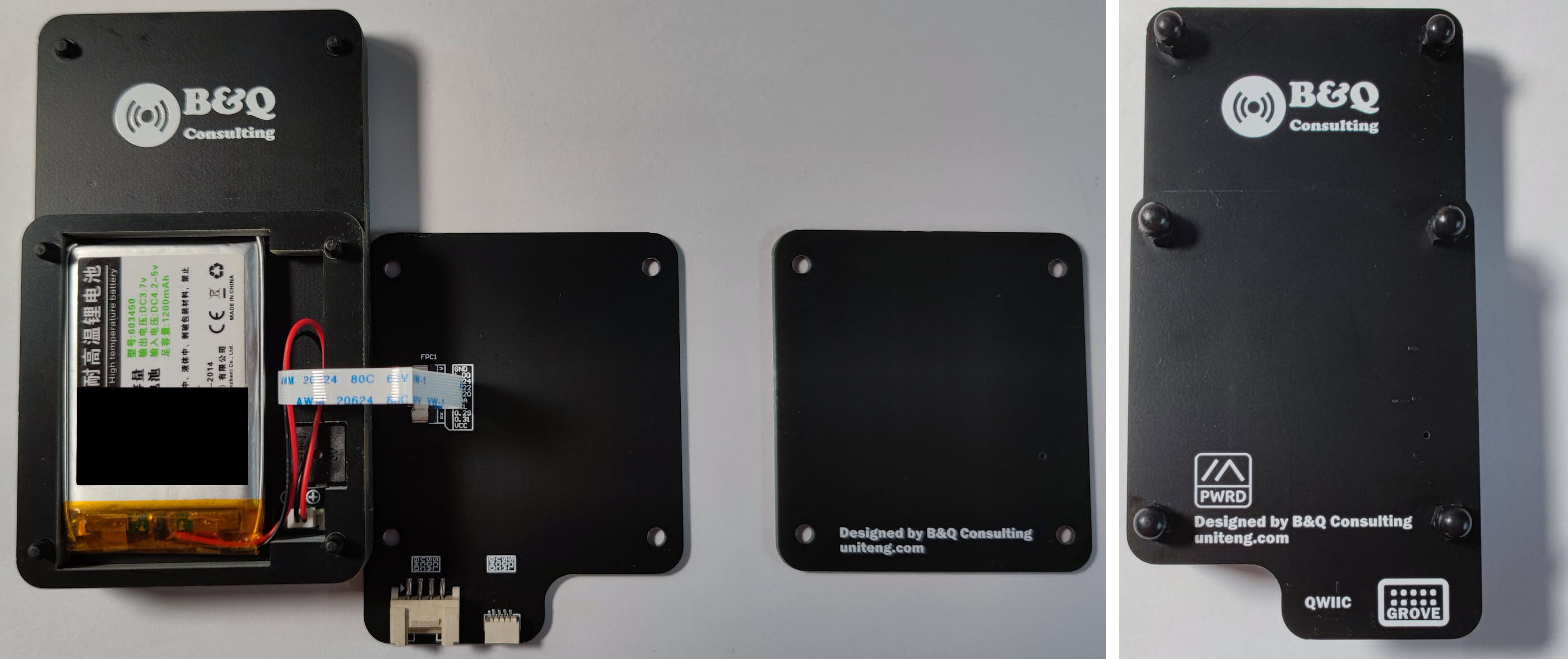
- Install the Optional 3.7V 603450 JST 1.25mm Rechargeable Li-Polymer Battery. Then install the I2C expansion board on top of the battery. The 10cm FPC cable can be placed on the top of the battery. The FPC cable allows 180-degree bending. The battery cover that comes with the device is not needed in this configuration, please keep it properly.
![i2c_expansion_board_step3.jpg]()
Battery Life Related Settings
According to the Power Consumption Measurement, the settings related to battery life are mainly related to ATGM336H-5N Whole Constellation Positioning and Navigation Module (GPS) and 1.3 Inch OLED Screen.
- Typical power consumption for GPS is about 22.2 mA @ 4.3V
- Typical power consumption of 1.3 Inch OLED Screen is about 6.37 mA @ 4.3V
For GPS, you can increase the GPS Update Interval according to the actual situation to further reduce power consumption. More Information about GPS Update Interval: https://meshtastic.org/docs/settings/config/position
For 1.3 Inch OLED Screen, you can decrease the Screen On Duration (display.screen_on_secs) according to the actual situation to further reduce power consumption. More Information about Screen On Duration (display.screen_on_secs): https://meshtastic.org/docs/settings/config/display
Reference
- RegionInfo. Retrieved Feb 20, 2023, from https://github.com/meshtastic/firmware/blob/afc75b25529590253c513f19e4b6f6f0ef94bf95/src/mesh/RadioInterface.cpp ↩︎
- Meshtastic Project. Retrieved Feb 13, 2023, from https://meshtastic.org ↩︎
- Grove I2C. Retrieved Jul 23, 2023, from https://wiki.seeedstudio.com/Grove_System/#grove-i2c ↩︎
- Adafruit STEMMA QT. Retrieved Jul 24, 2023, from https://learn.adafruit.com/introducing-adafruit-stemma-qt/what-is-stemma-qt ↩︎
- Qwiic Connect System. Retrieved Jul 23, 2023, from https://www.sparkfun.com/qwiic ↩︎
- CardKB Mini Keyboard Programmable Unit V1.1 (MEGA8A). Retrieved Jul 23, 2023, from https://shop.m5stack.com/products/cardkb-mini-keyboard-programmable-unit-v1-1-mega8a ↩︎