The last log on Rev. 2 got a bit into the weeds. That's my bad. Another product of my late night brain but hopefully you got the gist... These posts always take way longer than I think to write because I keep thinking of things I want to include!
Anyway, hopefully this log will be less rambly because today I tested out the last core feature of the CRAPi2040 board: LiPo Charging.
Spoiler: I nailed it first try :D
Nothing ever works first try so this is sort of a big deal for me.
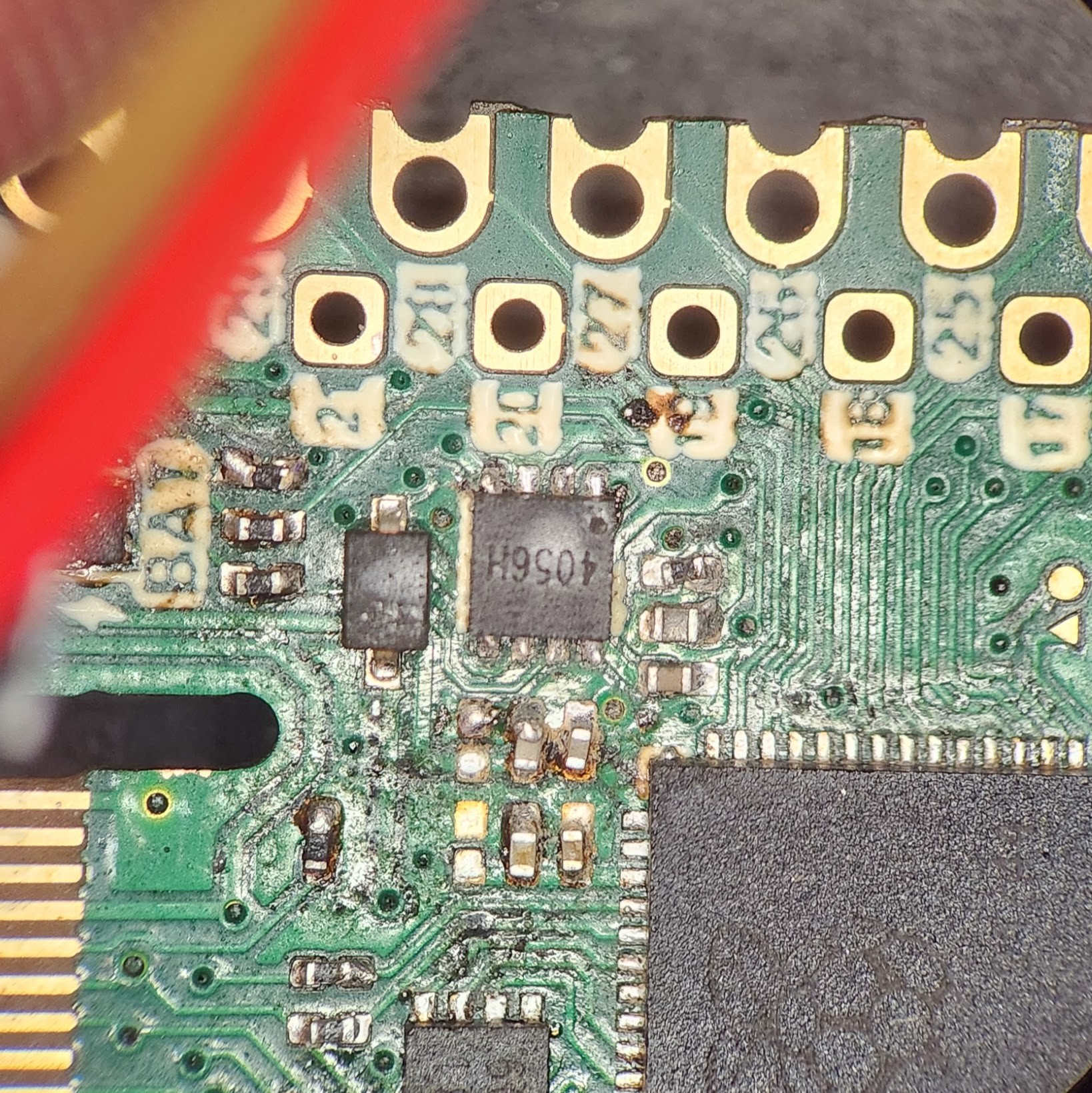
Here's an up close, but crusty, shot of the LiPo circuity. Sorry about that.
I was pretty deliberate in the choice in my charging IC. I had two primary criteria:
- Small as possible
- Constant Current and Constant Voltage Charging.
This random chip that I picked from LCSC does both of those things... Well, I am 100% it does the "being small" part well. Only about 80% sure on the CC feature as the entire sheet was in Chinese and the PDF translation on Google refused to work for some reason. I got around that by using that cool live camera translation thing on my phone.
As a side note, this was my first experience with LCSC and it definitely has it's uses. If you can fill in the blanks in some of the translations you can find some really niche stuff. The main reason I went to LCSC is because Digikey didn't have any appropriately minuscule LiPo charging ICs. The shipping was reasonable too considering it's an ocean away. If you are looking for something very particular and haven't already, checkout LCSC!
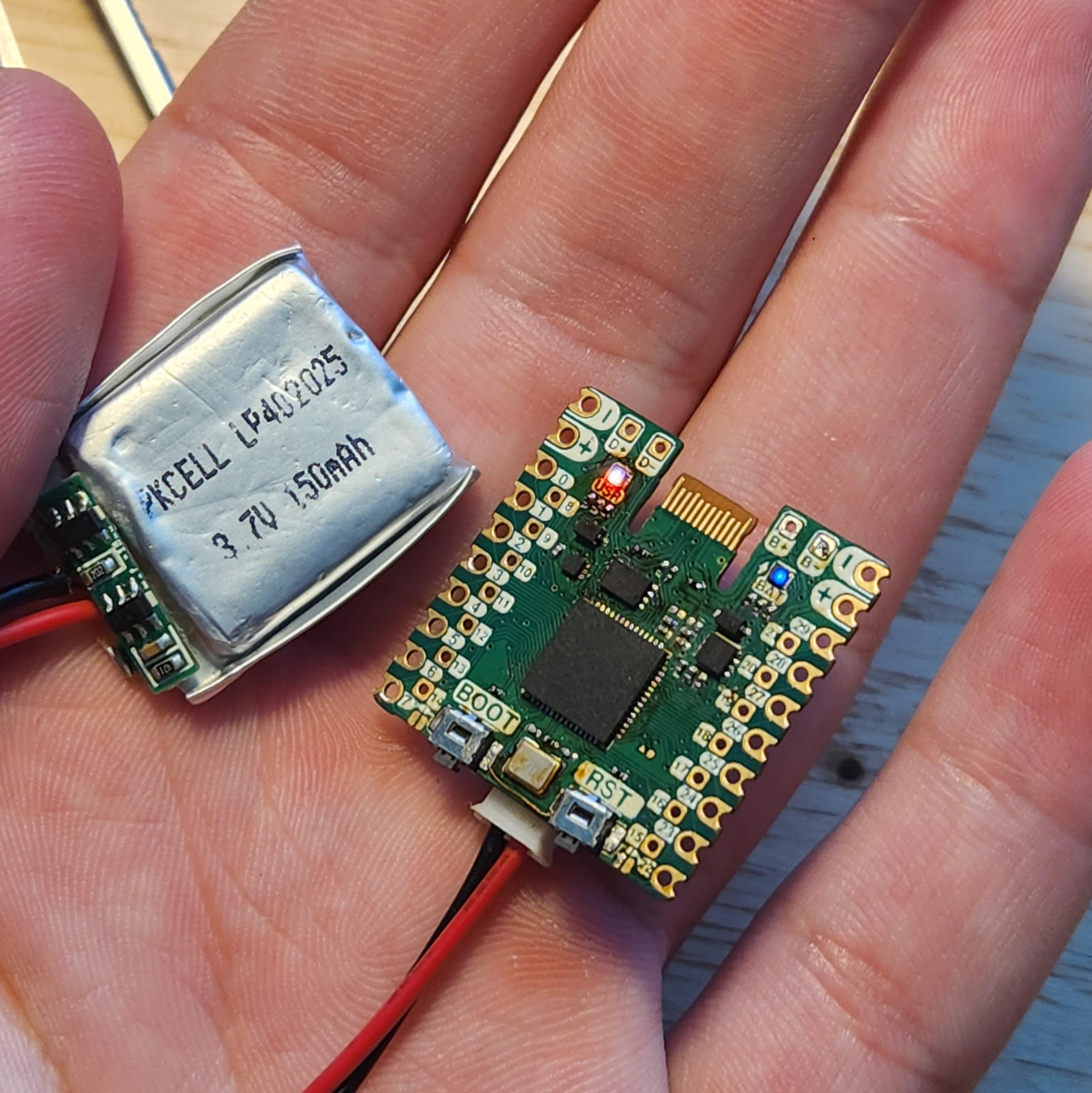
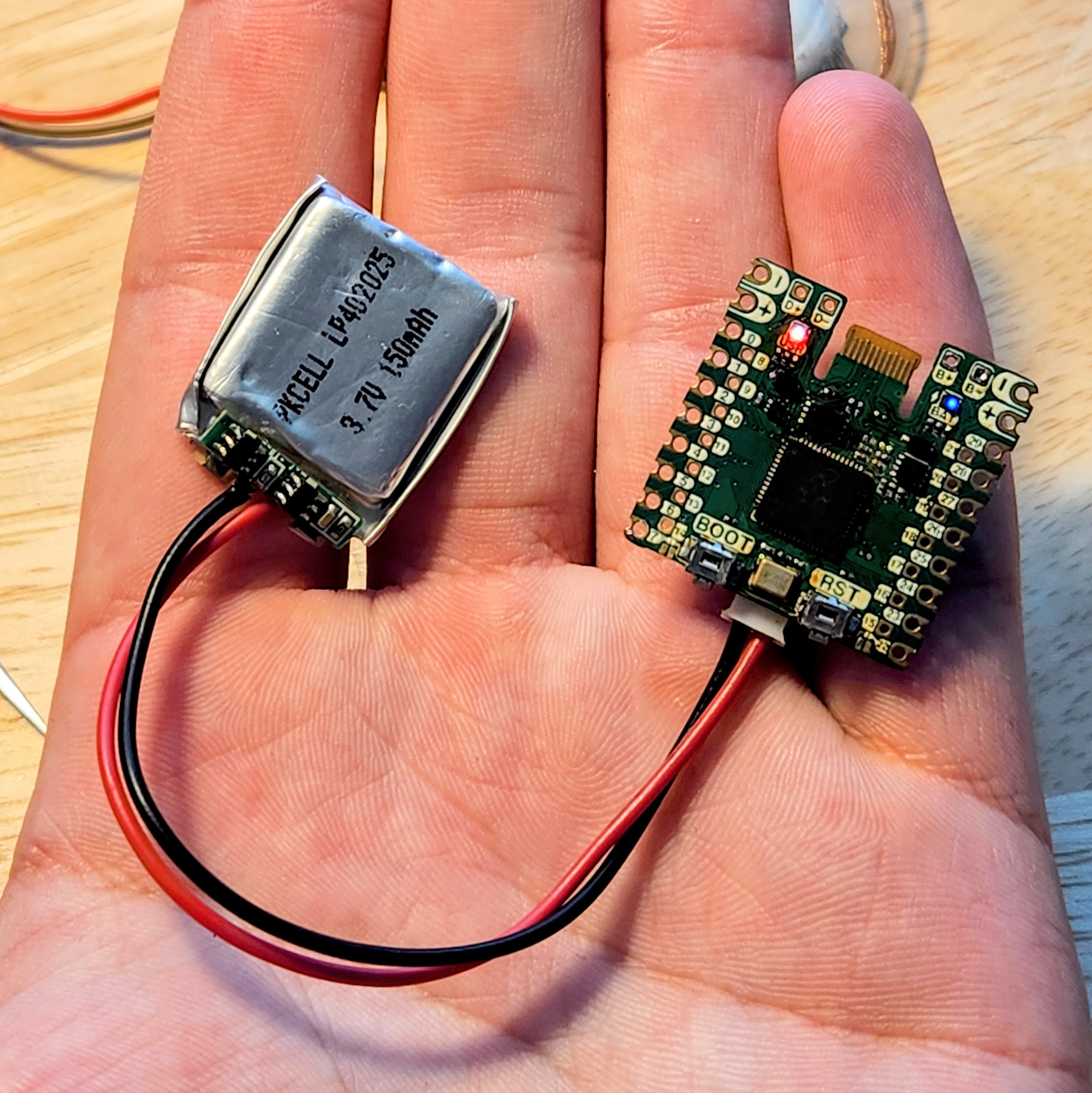
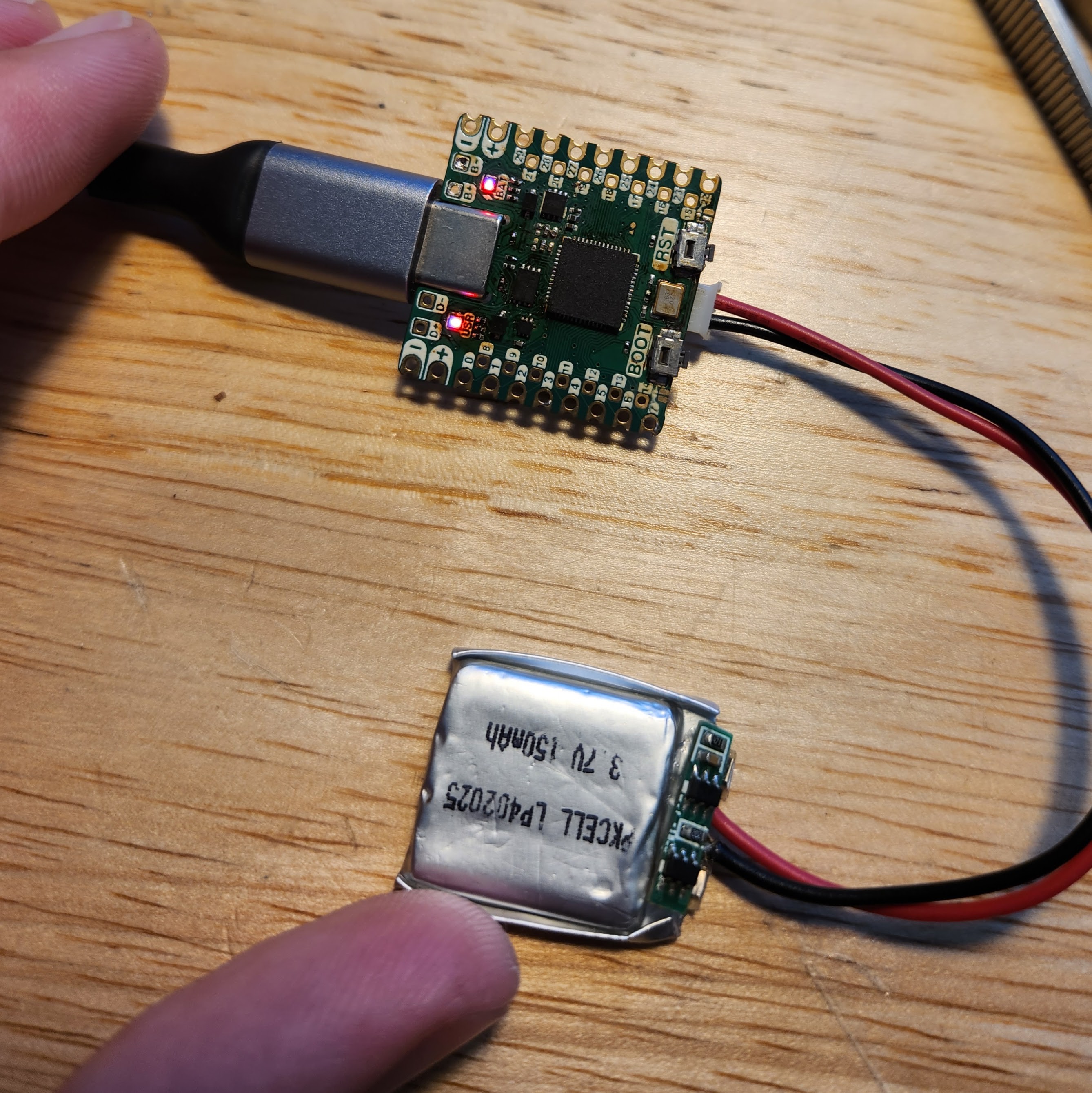
Here's the picture of success that made my day!
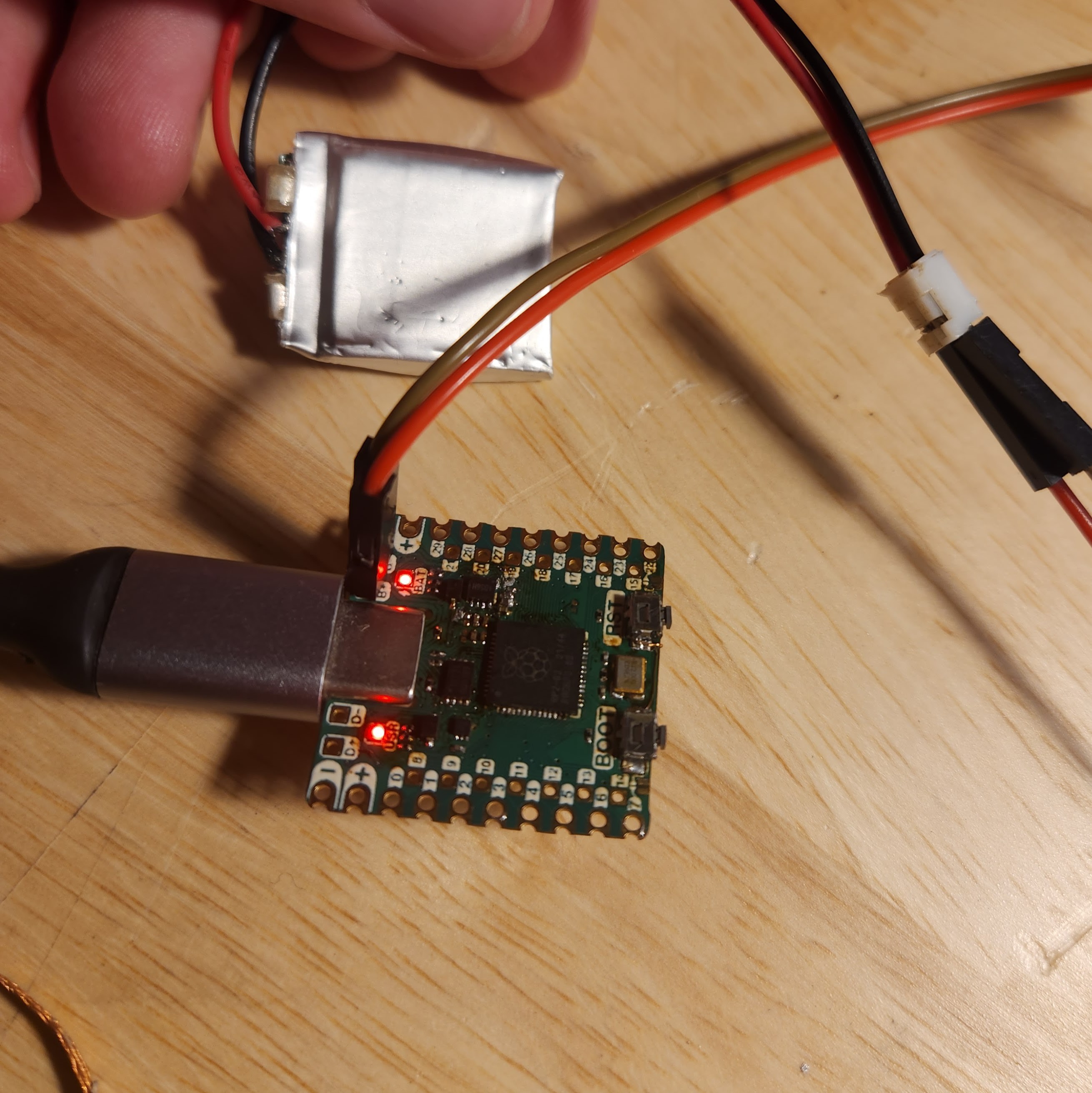
Look at those two beautiful RED LEDS!
The first red LED is the power but the second red LED is the charging indicator!! The bad boy popped right on the second I hooked up that beat up LiPo. Also, if it wasn't clear. That second LED (labeled as BAT), is RGB. The R and the G is hooked as the status LED for charing and the B is hooked up to pin 25 so that code meant to run on the Raspberry Pi Pico will port over well.
I wasn't patient enough to let scary LiPo try to charge all the way, so I jammed some jumpers onto some batteries that were already fully charged to see if I could get that green LED to show it's face.
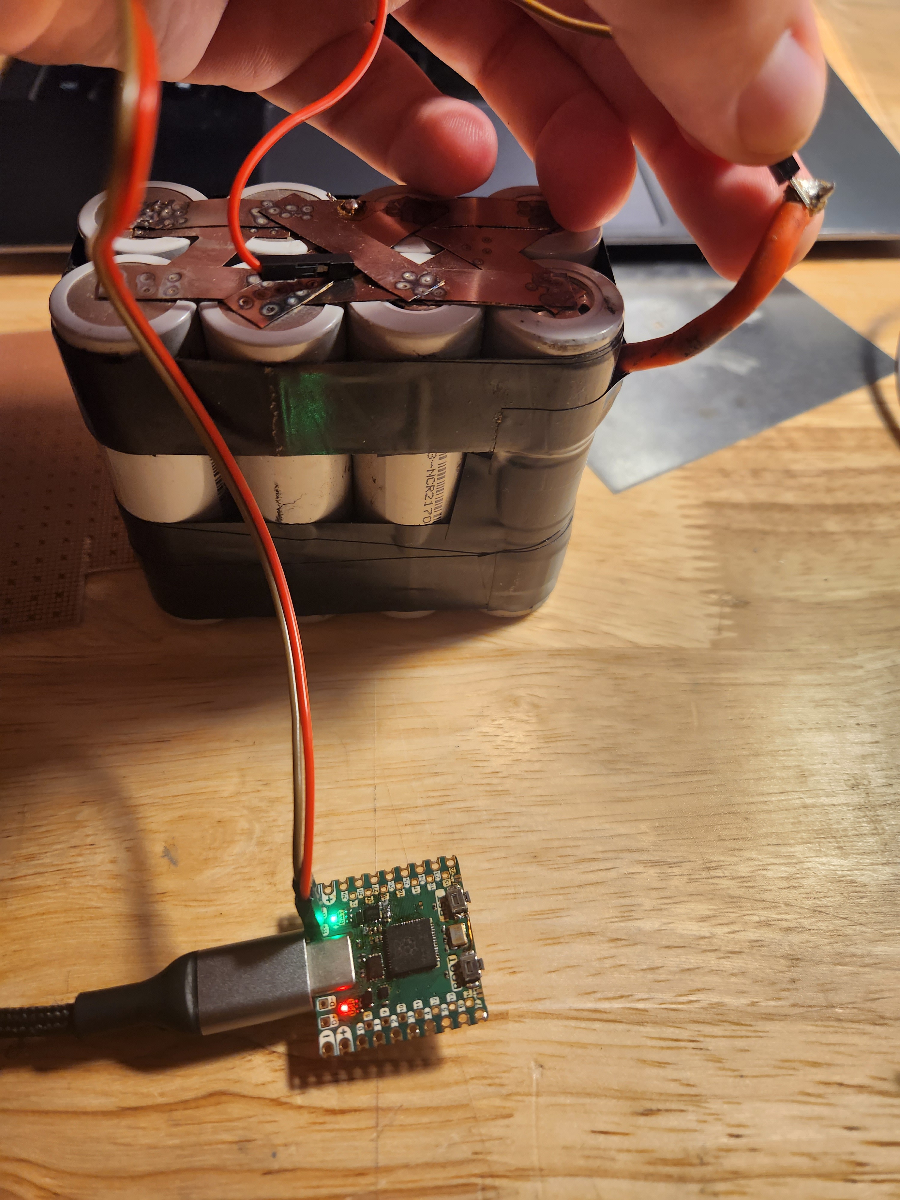
And there it is! YES. AMAZING. That feels so good. And by the way, this is only a 1 cell charger. The connection above is just testing one set of batteries in a 2S4P string.
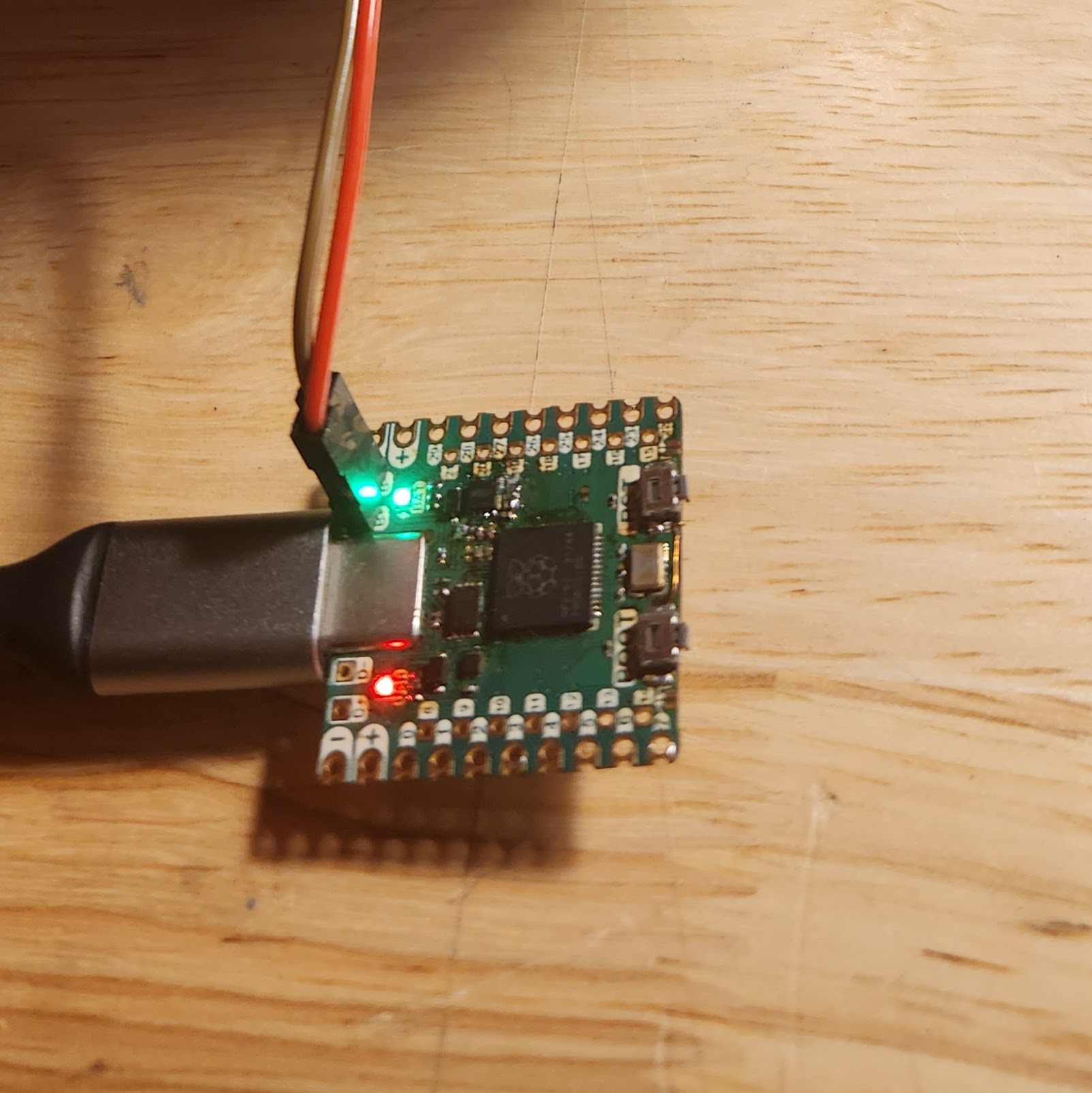
Green Green Green Baby!
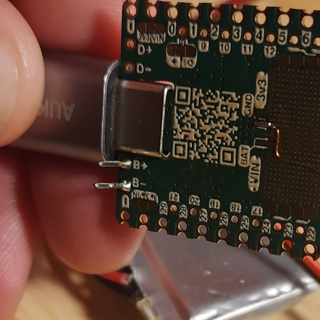
This also shows off one of the changes that I made to the Thads in Rev. 2 that I don't think I have mentioned yet. On Rev. 1 of the CRAPi board I had these really really tiny plated through holes which probably were sort of useless for getting solder to flow through.


In the second revision of the board. I made the holes way bigger. This is for two reasons:
- It will probably help when soldering the Thads to other boards
- AND they are the perfect size for those bread board jumpers that everyone uses.
The picture below sort of shows what I am talking about from the bottom view. The holes are just just tight enough to use as a friction fit but that's probably a bad idea. Also note the 0.1 inch spacing!
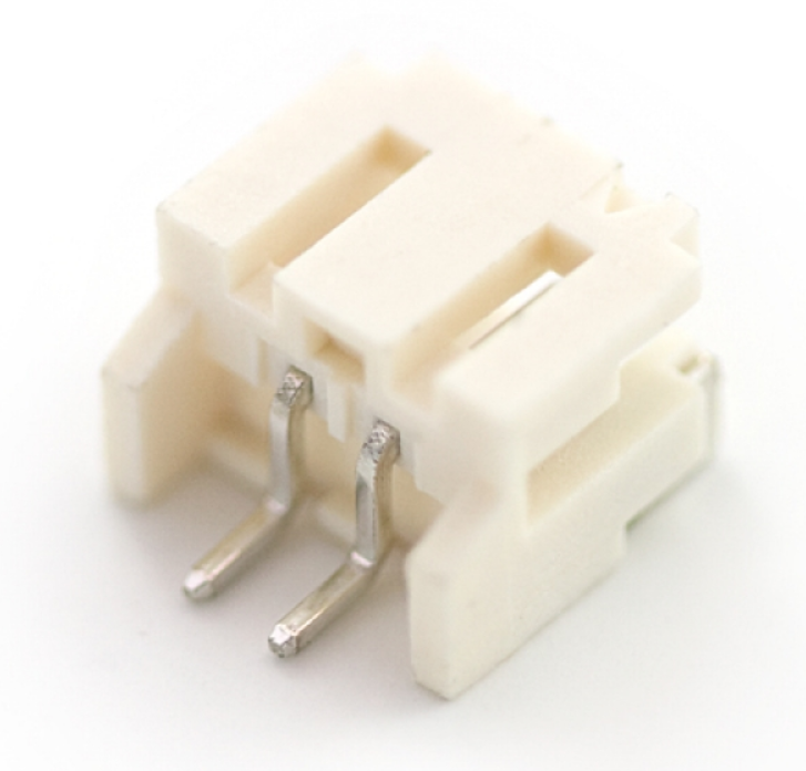
In all of this excitement I almost forgot to test another feature that I labored over in Rev. 2 on the ProtoGrid. I succeeded in jamming a (somewhat hidden) right angle JST connector footprint onto the CRAPi board! You know, this one:
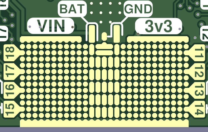
Direct your attention to the BAT and GND labels. Those aren't just for show! Those skinny little pads are basically the exact same width as the leads of the JST-PH connector shown above. Obviously, I didn't have much room to work with so I wasn't sure if this would even work.
 Again, to my surprise: the footprint worked perfectly. The front anchor tabs of the connector have no problem being soldered down to the GND rail at the bottom of the ProtoGrid. I'm pretty sure I was designing this on a train to Chicago in the middle of the night. So, I don't really remember designing this, but I am glad it worked out!
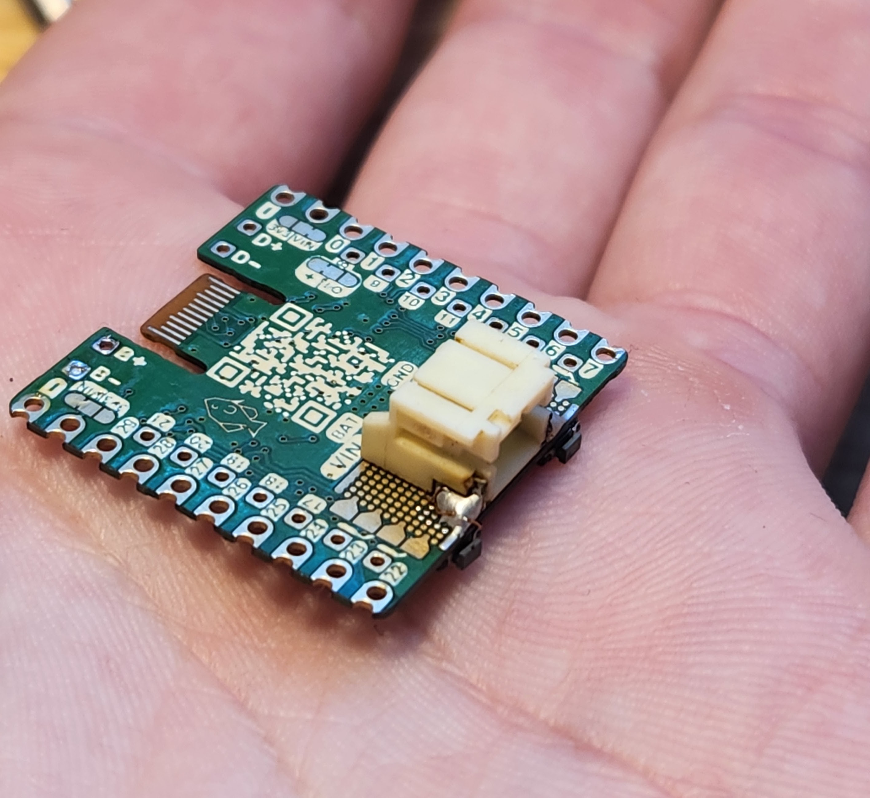
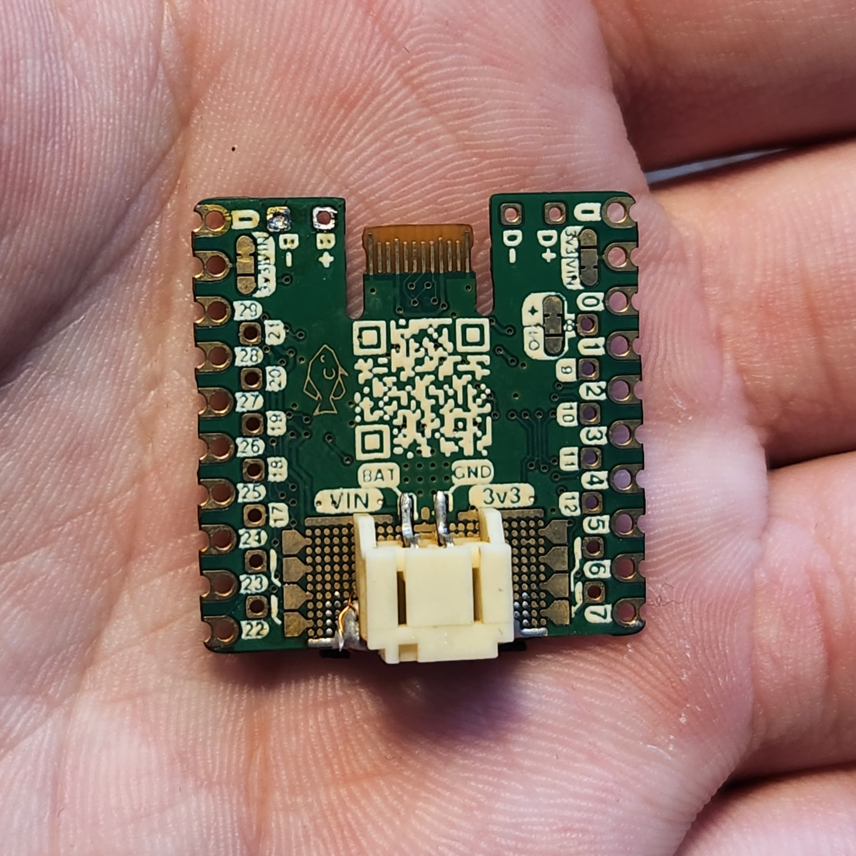
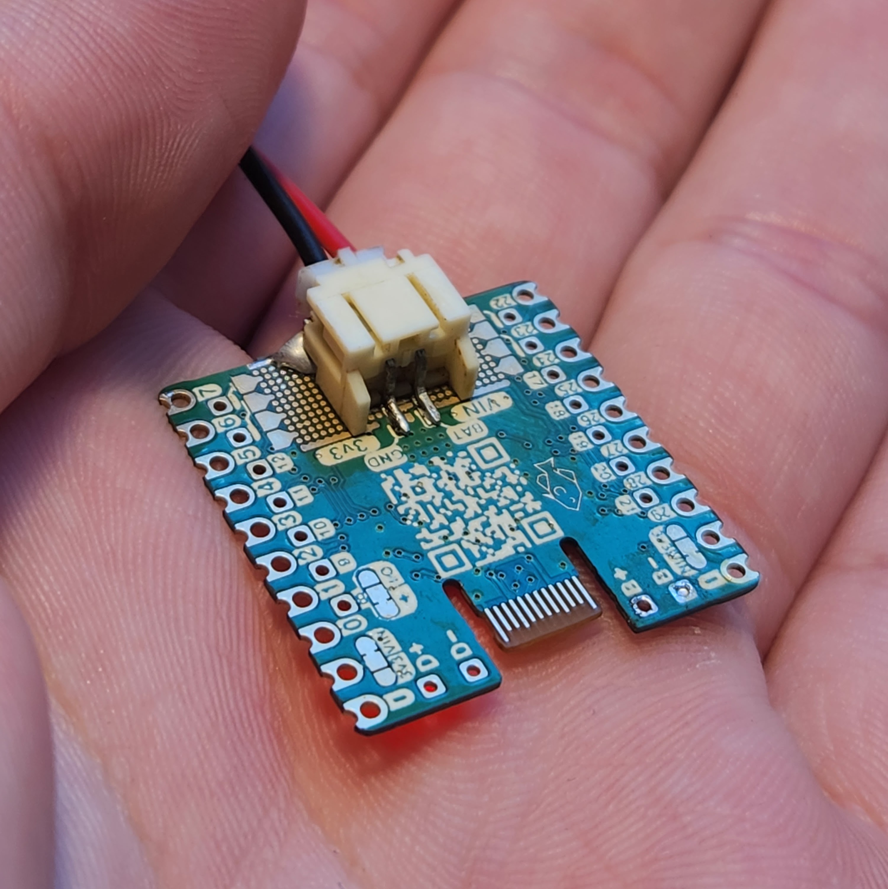
Sorry for all the picture spam but I am just so thrilled. It just looks so CLEAN. I love it. The connector takes up the entire ProtoGrid, but hey, that's why I broke out the battery connections to more than one place. The CRAPi board is about flexibility, remember?
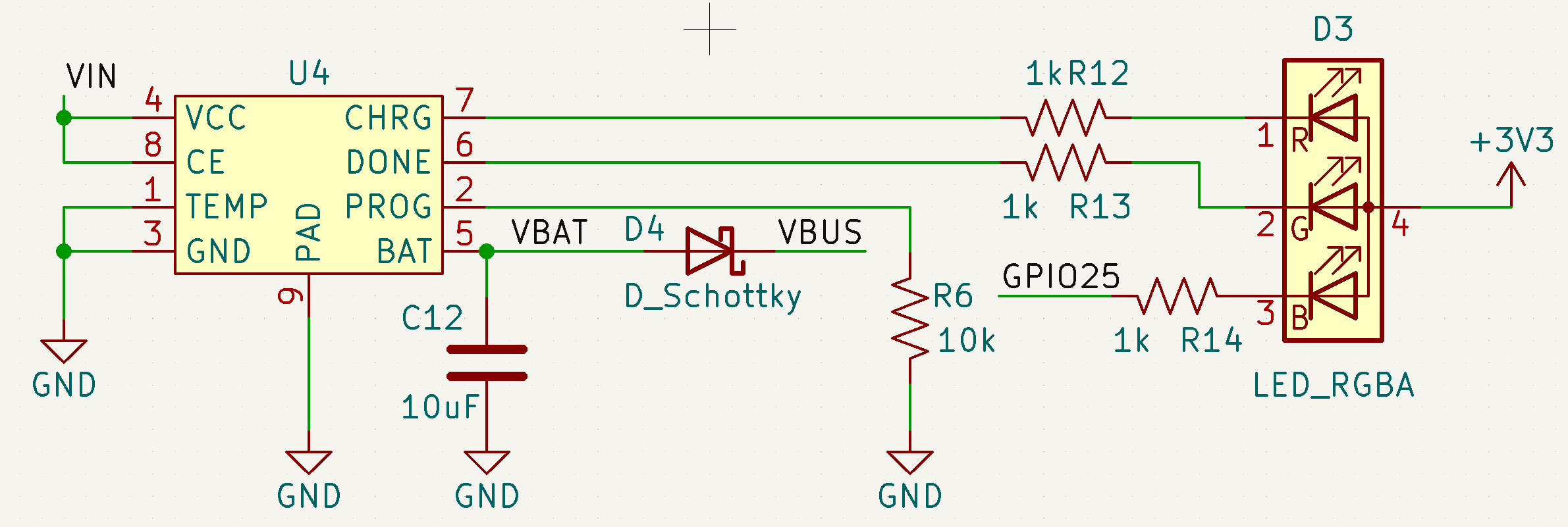
I am also happy to report that the power source switching seems to be working. Starting off on battery power and plugging in USB power the red charging LED illuminates. It shuts off when I remove the USB as well. Repeating this cycle more than once seems to yield inconsistent results so more investigation is required.
At least it works once though! I had never thought about the circuity needed for power supply switching on LiPo enabled dev boards. I took the easy route out and just slapped a Schottky on the battery terminal (cheap, remember)? Because of the diode drop it means a less than optimal voltage range from the battery. However, it does mean one less item on the BOM because I am using the same type of diode for reverse polarity protection on the VIN line.
If the Schottky ends up being a problem then maybe I will consider finding a tiny P-FET to handle the power supply hand off a bit more elegantly.
What's next?
Either way, I think that wraps it up for this log! At this point I have tested everything that I needed to on Rev. 2 of the CRAPi board!! I am so excited to have this project asymptotically approaching "complete" so that I can start using it in my other projects.
I am thinking about some base boards and adapters that could be useful for the CRAPi board as well. I am a big fan of the "use only what you need when you need it" mentality, and the idea of adding on beefier functionality to the CRAPi board in the form of a baseboard or add ones would be cool. I am thinking maybe a little back pack that includes mounting holes, or an on board regulator with a crazy wide input range.
I'll also be giving PCBWay a try for Rev. 3 to see what their quality looks like. Armed with my microscope I am super pumped to do a comparison and see how they handle some of my wacky ideas.
What do you think?
That being said, I have a mental list of bug fixes to make in the next revision of the board. However, it has occurred to me that more than one person might want to use one of these things (thanks, James!) so I am wondering: what cool ideas do you have to make the CRAPi board even better?
Let me know!
 Chris
Chris
Discussions
Become a Hackaday.io Member
Create an account to leave a comment. Already have an account? Log In.