 Marsupilami
One of the nice things about this whole concept is that -by coincidence- there is no need to mess with a power supply / regulator circuitry for the PXIe instrument.
In general a module needs a +12V and a +3.3V rail and a +5V with negligible current draw. In case of the PXIe-5644R the spec sheet says the following:
+3.3V..............4.9A (5.3A max)
+12V................3.3A (4.2A max)
Luckily the SATA power lines from the ATX power supply contain all three. I couldn't find what's the story behind most storage drives only using +5V and +12V to the extent that adapters from the old 5pin power connector are very common. I wonder if I am just not aware of disks using 3.3V or it was for a future use case in the standard that never become reality.
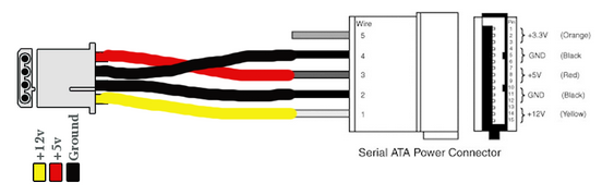 Anyway, the connector has the 3.3V rail and the PSU will supply it so the only thing is to check current ratings. This happened to be more difficult than I though, and I found contradicting information on the interwebz. The old(-ish) SATA standard I have defines the per contact minimum rating at 1.5A. On the 15 pin SATA power connector there are 3 contacts for each positive voltage, and 2x 3 shared for ground. Since the 5V current draw is either zero or very small we can ignore that, thus both 3.3V and 12V have 3 contacts each in both directions giving a combined limit of 4.5A per rail.
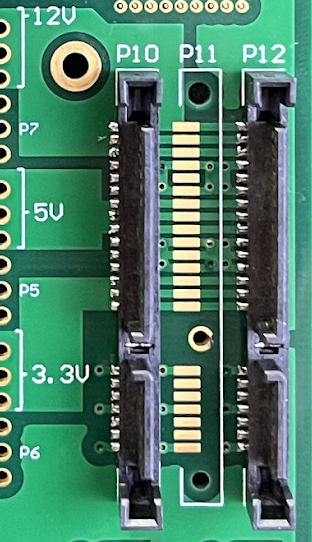
I put 3x SATA power inputs on the PCB, but only populated 2, for a maximum of 9A input per power rail over the connector contacts.
(As a side note it is fortunate that 2 connectors is enough, because I spaced them too close on the board, not taking into account the protruding part of the cable connector. Since 2 is sufficient, I just left the middle one unpopulated.)
The PXIe module has its own power conditioning and voltage regulation stage, but I still felt like I had to do something to compensate for the fact that the power is not delivered directly from a low impedance trace on the backplane, but through ~2 feet of wire, from a commercial psu. As a wholeheartedly half-a$$ed solution I put a 100uF tantalum polymer cap on each input voltage rail. I read something somewhere...
 I'm using 16 AWG wire, which is plenty thick and the MSI MPG A650GF psu can supply enough power for 2 PXIe-5644Rs.
Since I didn't want to connect any disks to the same SATA power lines, I decided to make new point to point cables for them


Discussions
Become a Hackaday.io Member
Create an account to leave a comment. Already have an account? Log In.