I bought a frequency counter, just because it had 6 nixie tubes. I am turning it into a clock. Plenty of similar projects have been done.
Frequency counter becomes Nixie clock
Turning an old device with Nixie tubes into a clock
Turning an old device with Nixie tubes into a clock
To make the experience fit your profile, pick a username and tell us what interests you.
We found and based on your interests.
I bought a frequency counter, just because it had 6 nixie tubes. I am turning it into a clock. Plenty of similar projects have been done.
I made a short video showing the clock working:
The last parts arrived and I finally had some time. I soldered all the wires to all the boards. Six times 10 wires for the digits, six wires for the anodes and 2x2 wires for the two neon lights that act as a dot. Soldering everything together was a bit of a dirty job, I also lacked a few extra hands. But, it worked in the end.
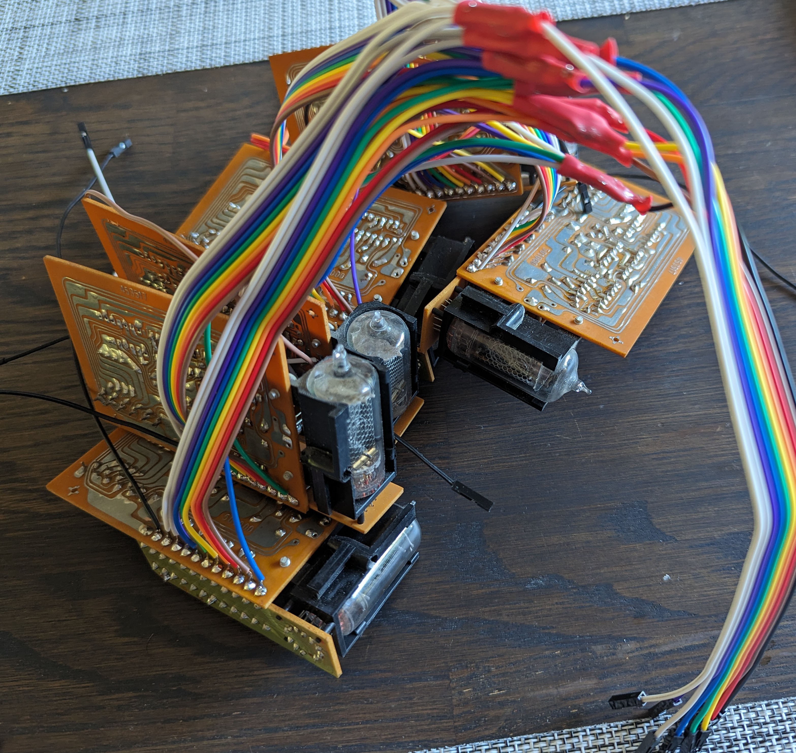
After checking all wires for shorts, I felt condifent enough to put the boards in and test them.
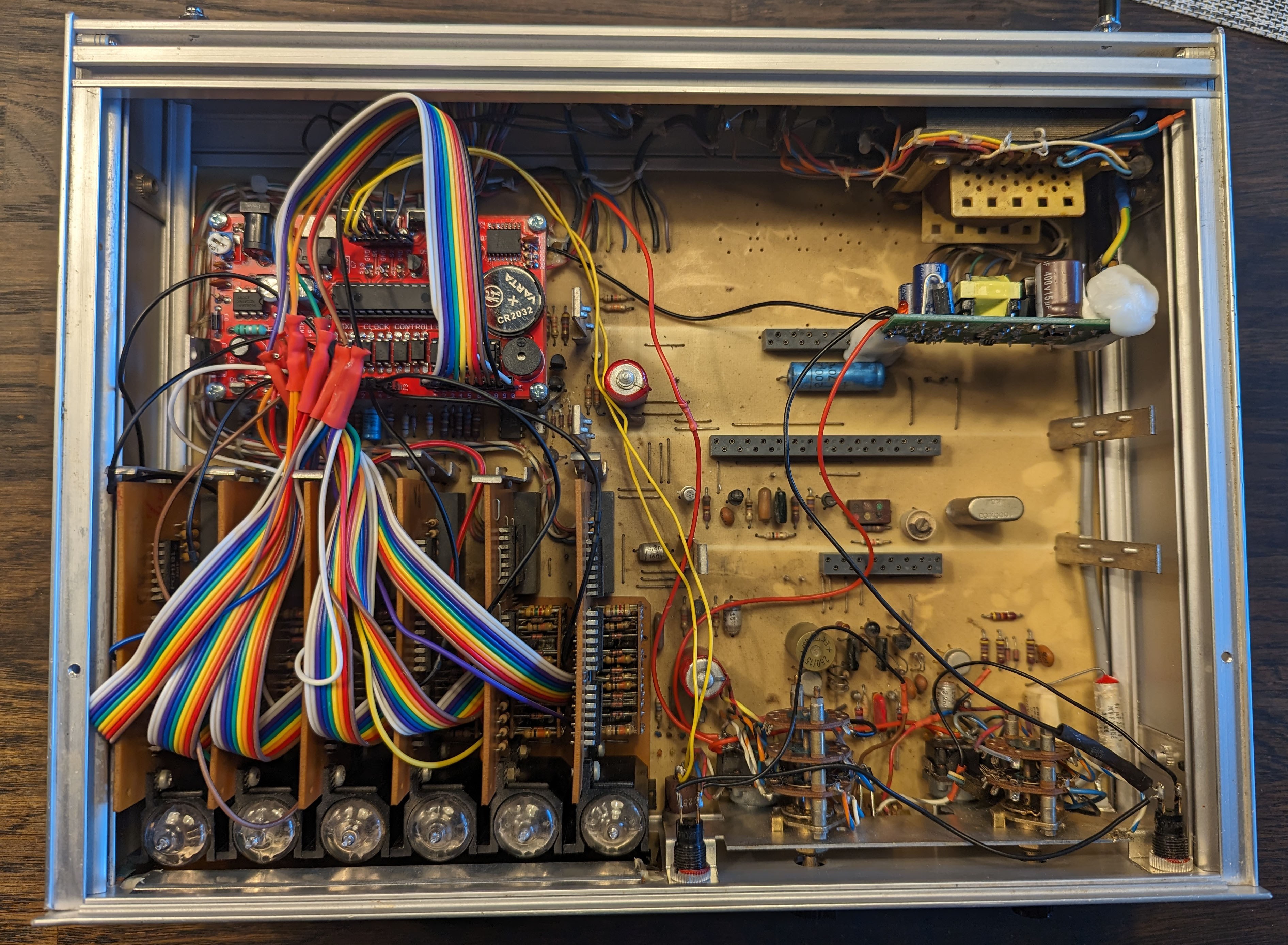
Of course, I had the numbers mixed up, but that was easily fixed. And then, I had a working nixie clock!
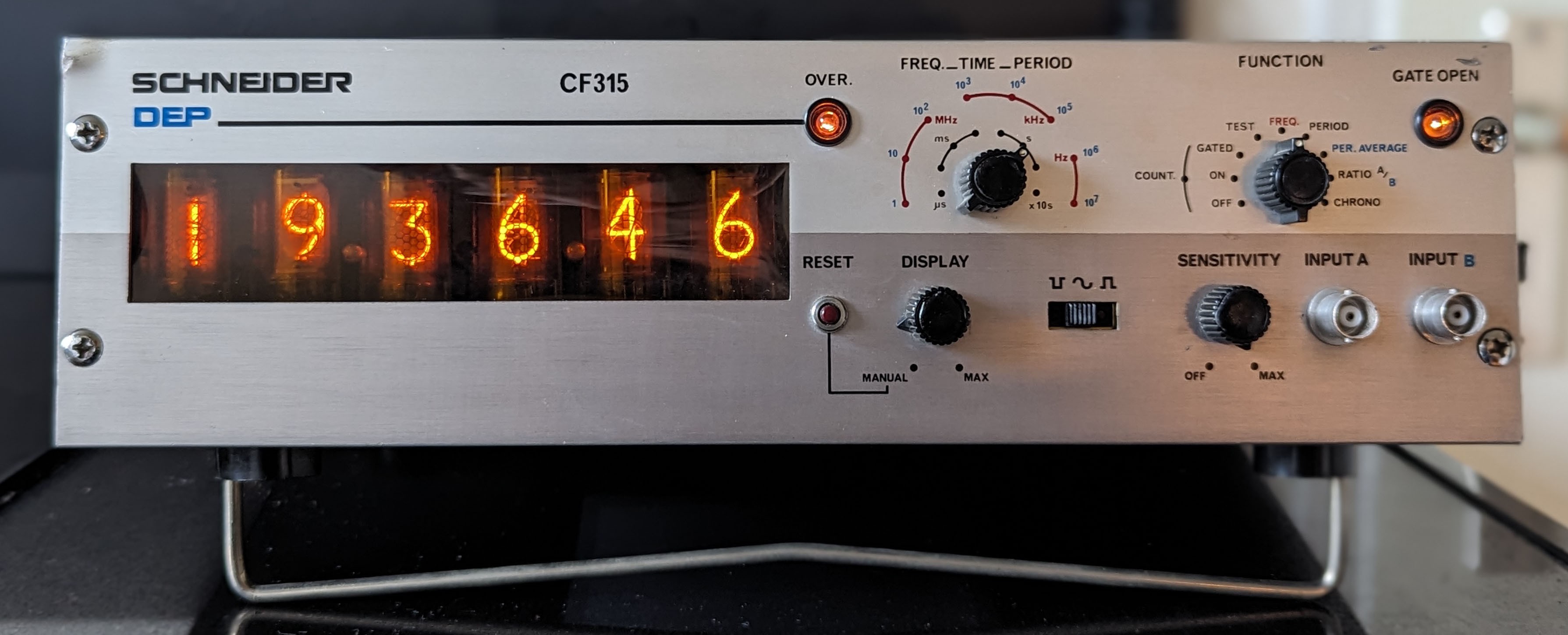
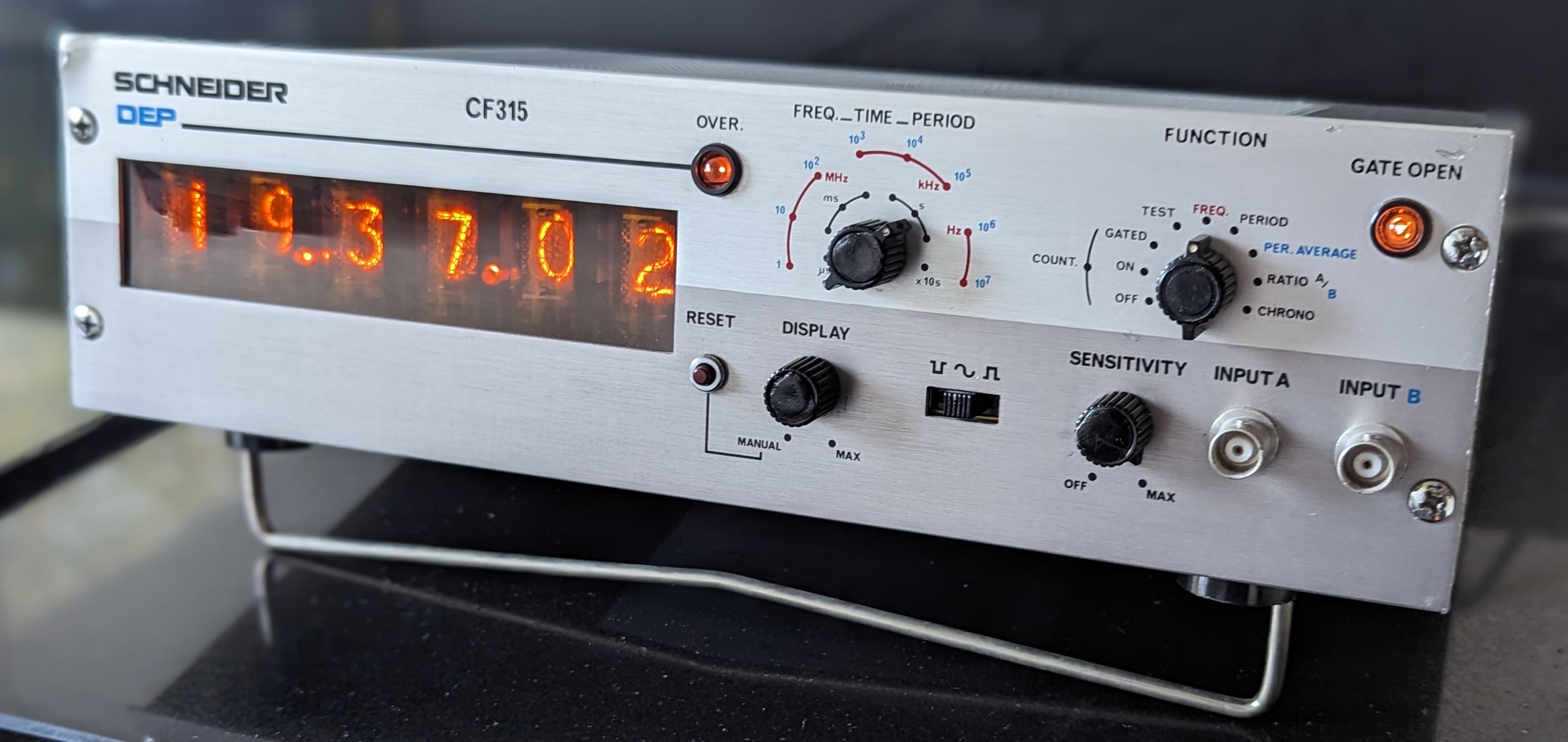
I've ordered some wires to connect to the nixies. They haven't arrived yet. I did some final prepwork.
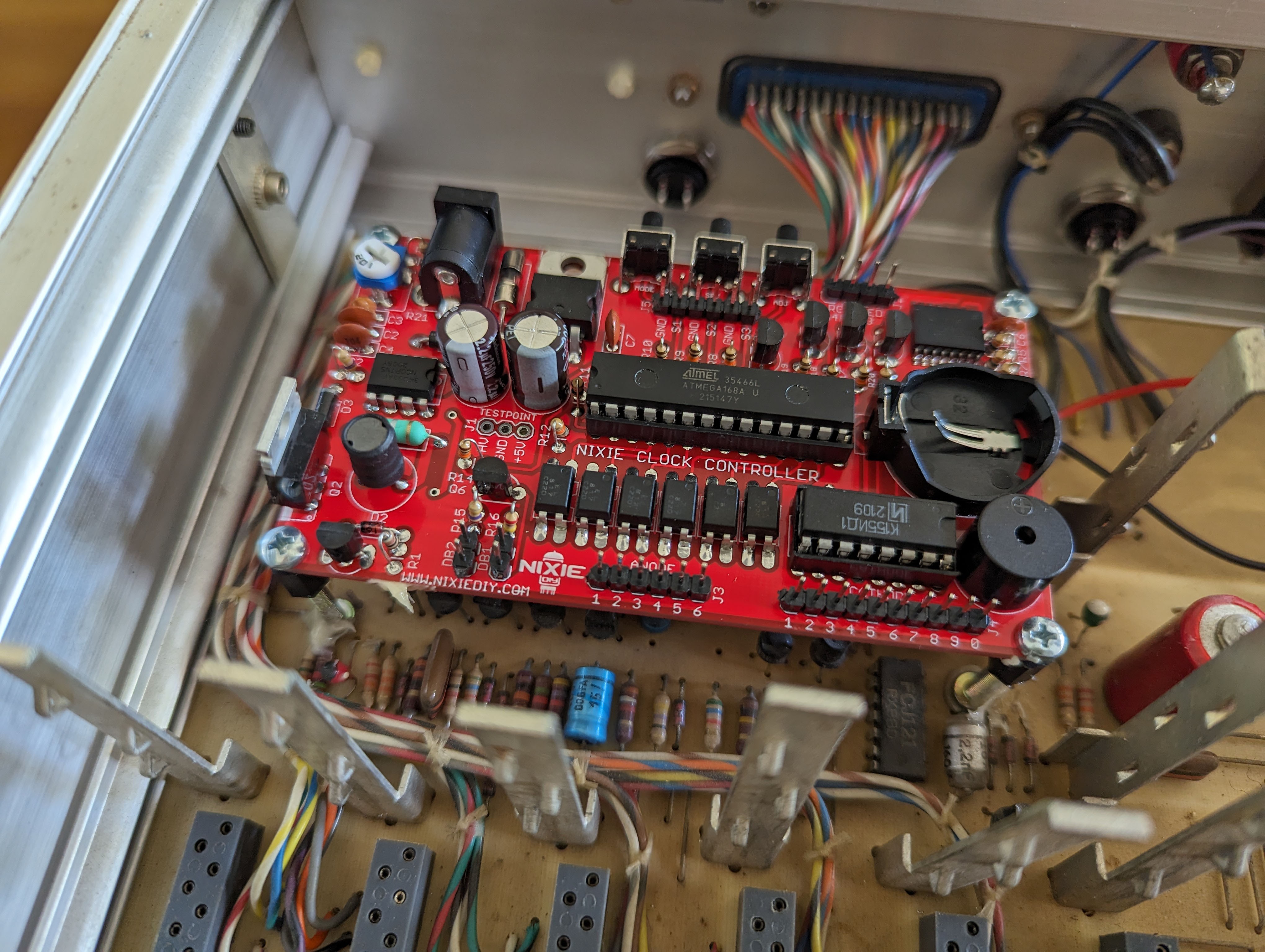
I put some screws on the nixie PCB and glued it to the existing main board using a two component adhesive.
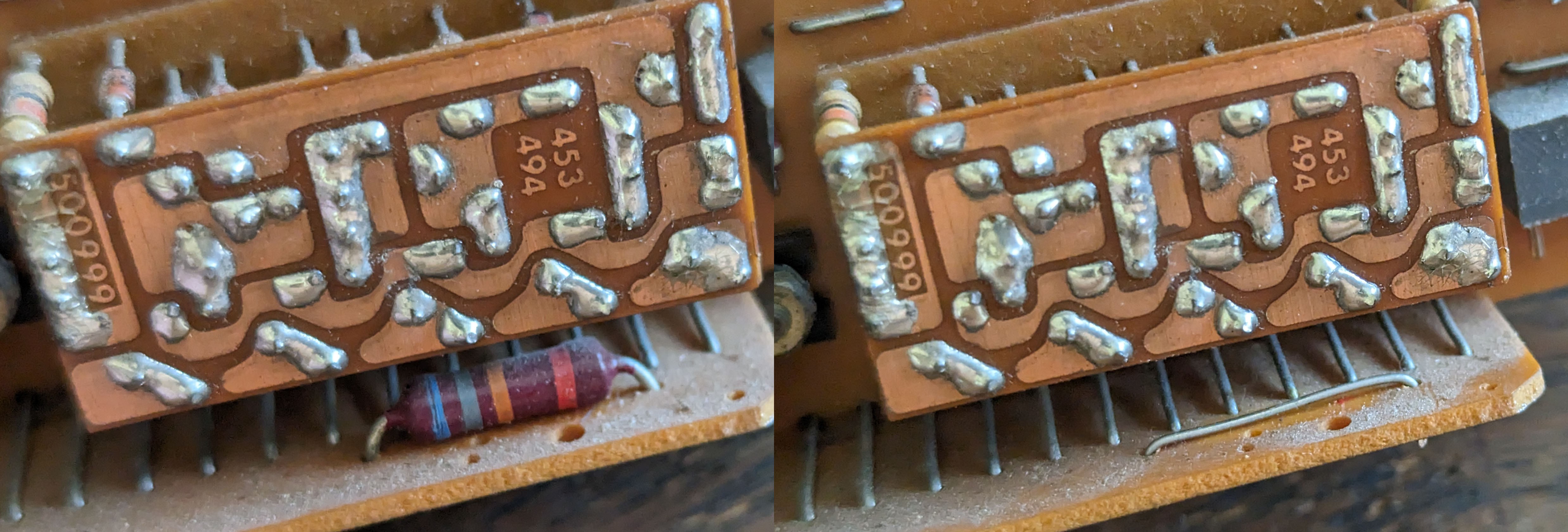
The other thing I did is replaced the resistor on the tube anode on the six nixie PCBs with a wire bridge. I also cut the traces from the kathodes so the tubes are no longer connected to components that are remaining on the main PCB.

I am still waiting for parts to arrive. But I did a few things. First of all, I took out the BNC connectors at the back and made the holes a bit wider to accomodate two push buttons.
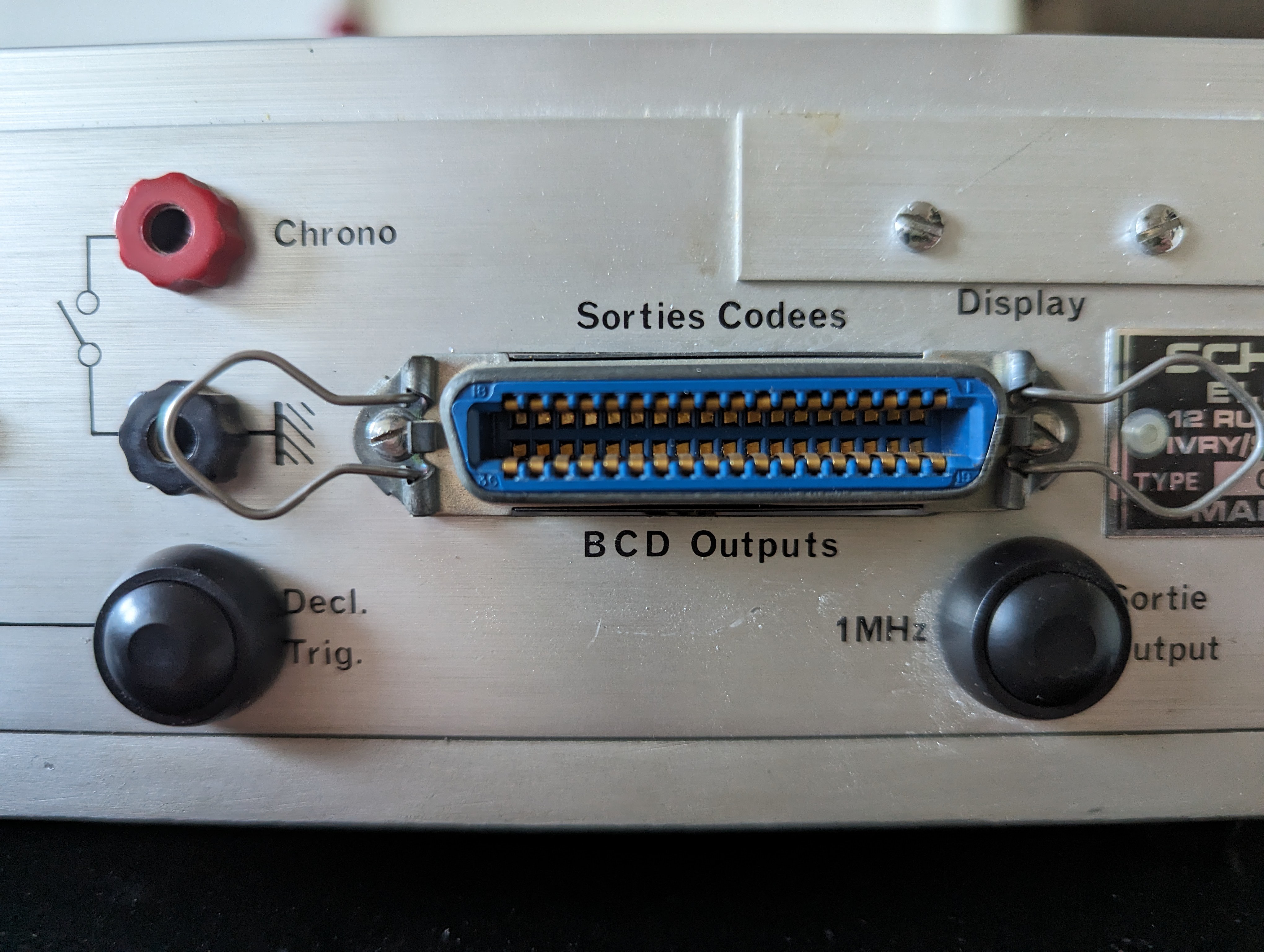
These are used to set and operate the clock. The third button is a button on the front.
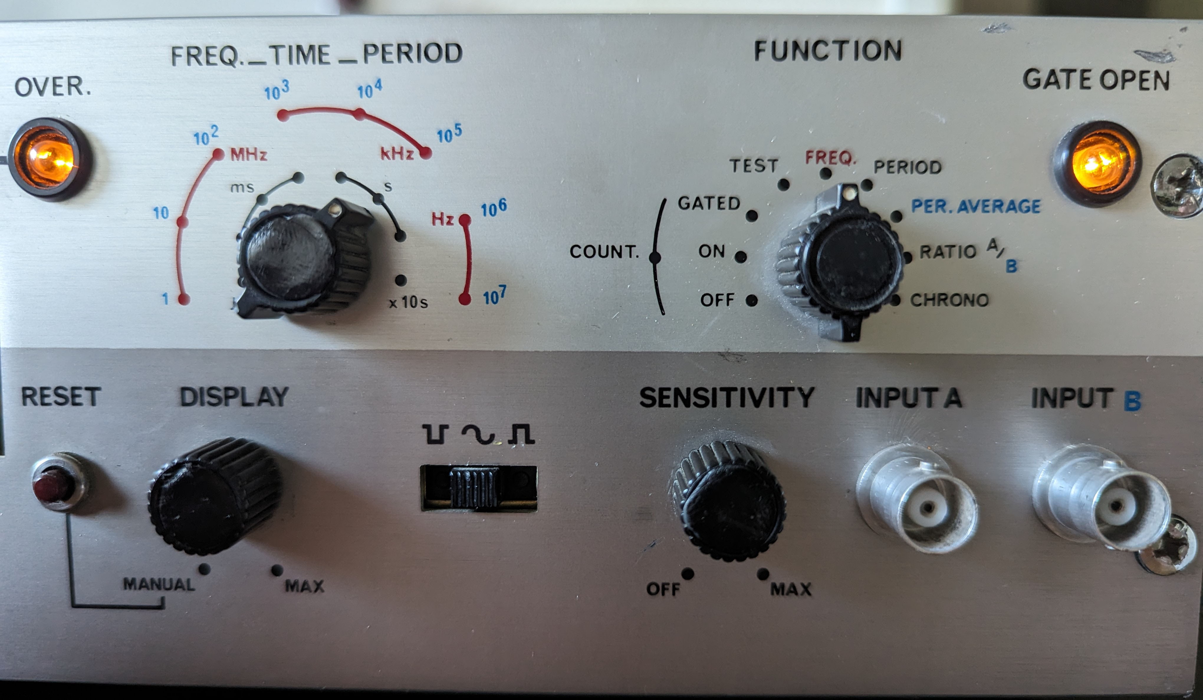
On the front, there are two selector knobs ("display" and "sensitivity") that are on/off switches with a potentiometer in one. The left one, marked "display", I wired to be the main on/off switch. The potentiometer is not used.
The "sensitivity" knob now turns the light(s) on/off. The potentiometer is used to set the brightness. Unfortunately, the potentiometer is in the MOhm range, so there is very limited movement until the power drops below the light being visible. I also added a resistor to dim the light a bit, as I worry it will burn if left on 12V for too long.
Since there are two lights, I also repurposed the switch to select up or down flank. This switch has three positions. In the left, the left light goes on, in the right the right, and by adding a few diodes now both lights light up when it's in the middle position.
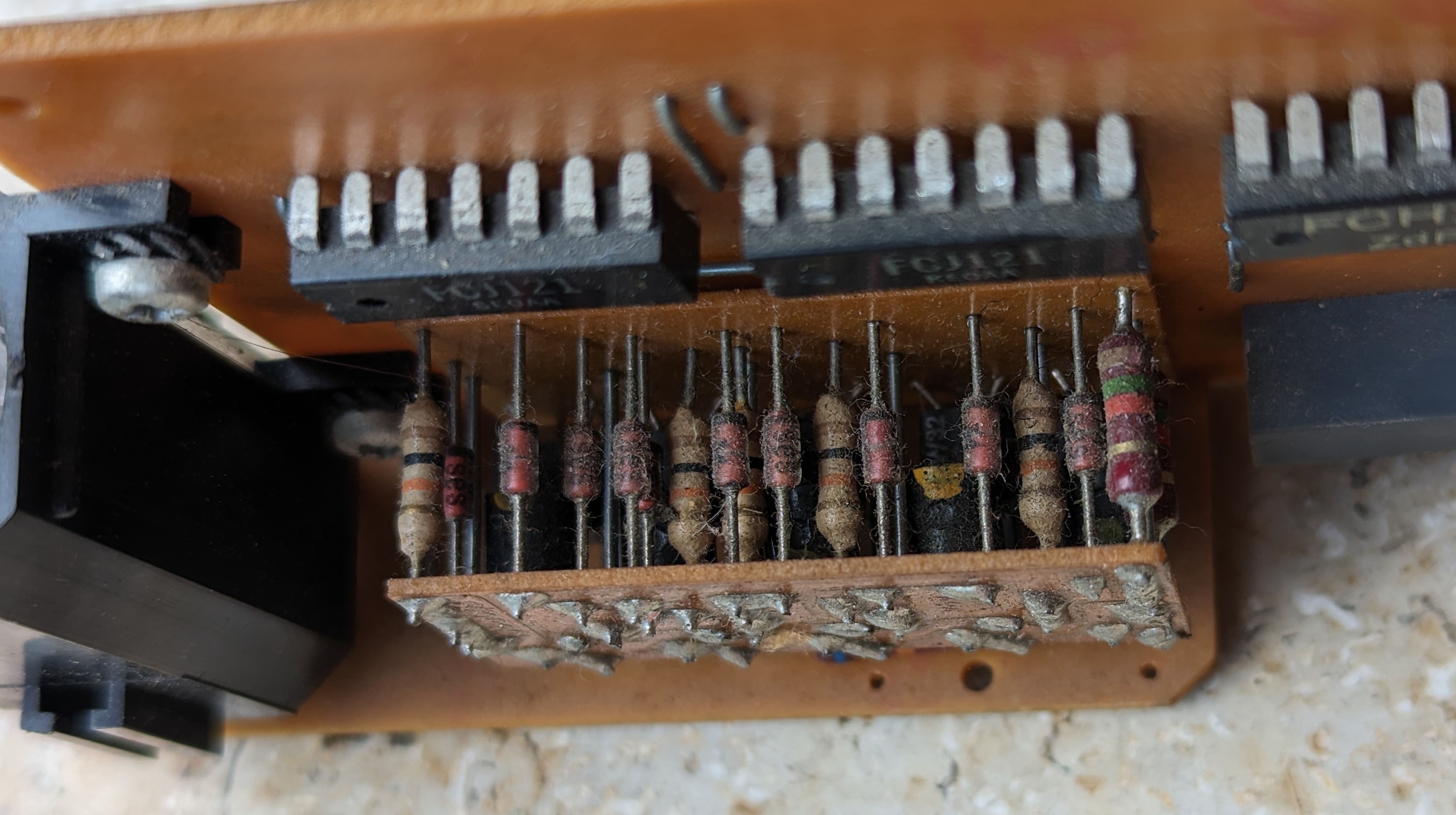
The comment on the last blog posting was that the "block" of components on the nixie boards could be the decoder. I took a picture of it, also showing the buildup of many years of dust. Indeed, we see resistors, diodes and transistors there, neatly packed together.
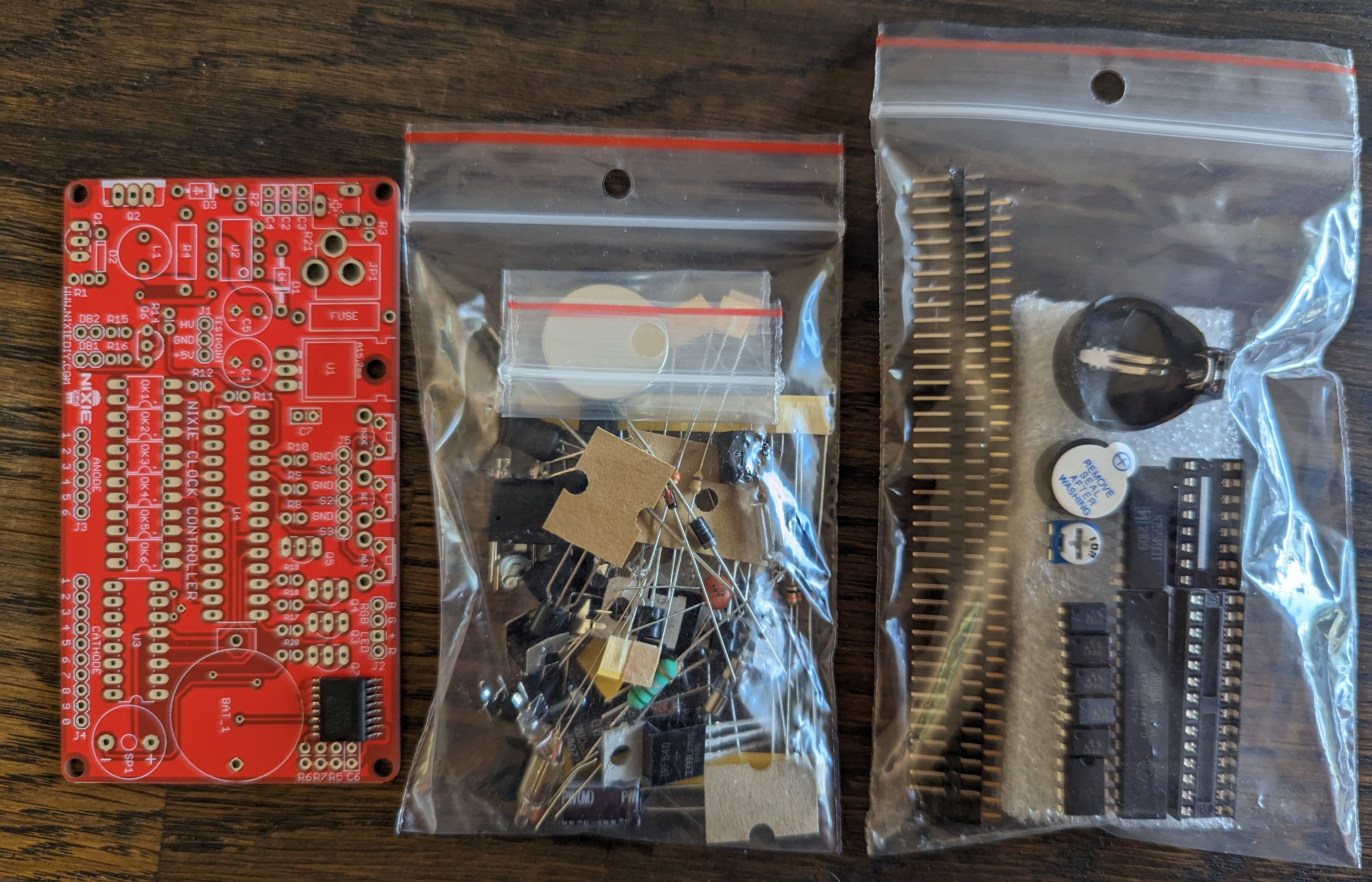
Today, the nixie kit arrived from http://nixiediy.com/. It came with a very nice manual, that reminded me a bit of the Gigatron manual I wrote.
I quickly soldered everything together and checked the voltages when hooked up to the buck converter. All was fine.
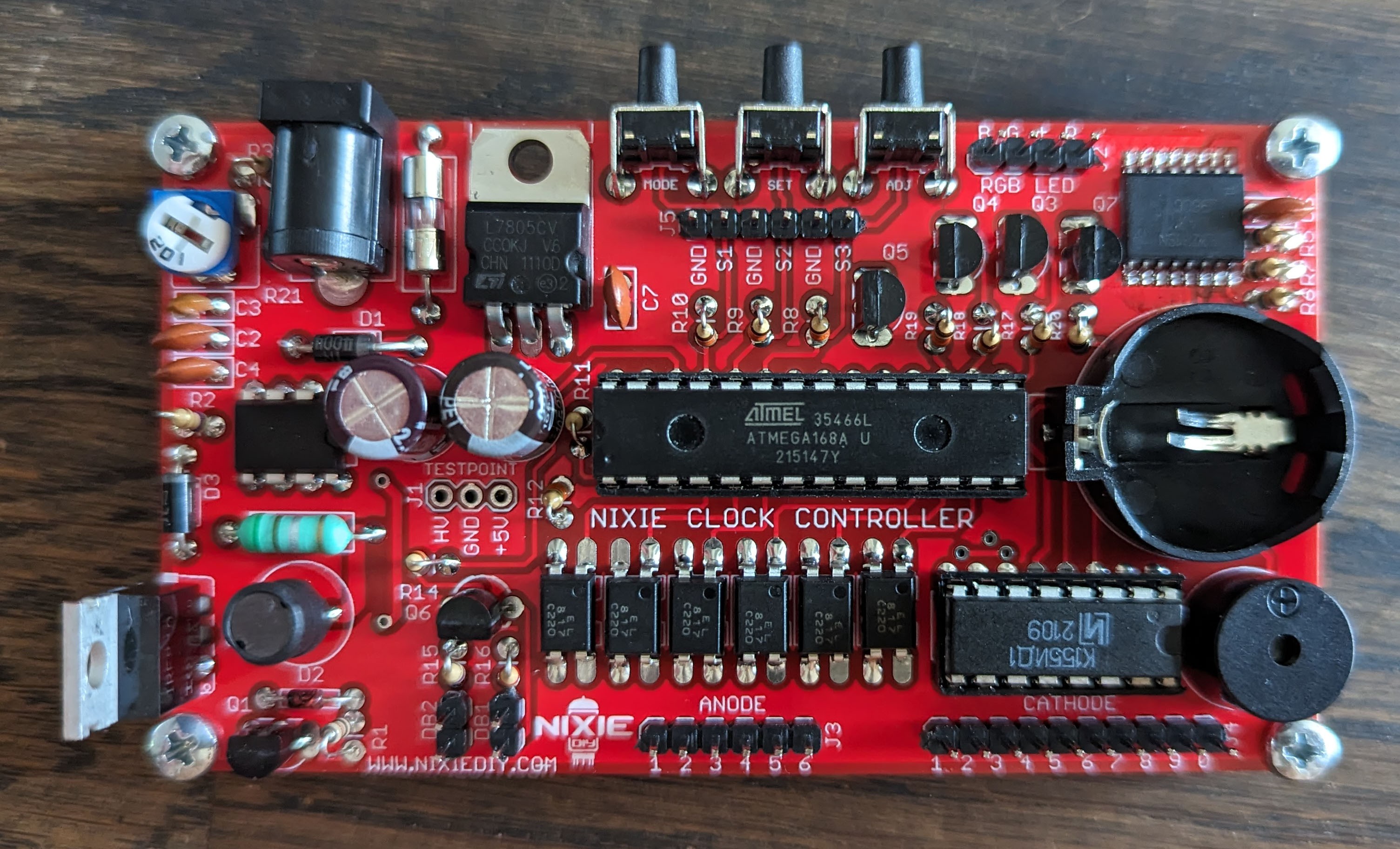
I'll insert the battery when it's fully hooked up. I am waiting for some wires to arrive to connect the tubes. But I can already start with putting this PCB in the enclosure, putting in the buttons and connecting the lights on the front panel.
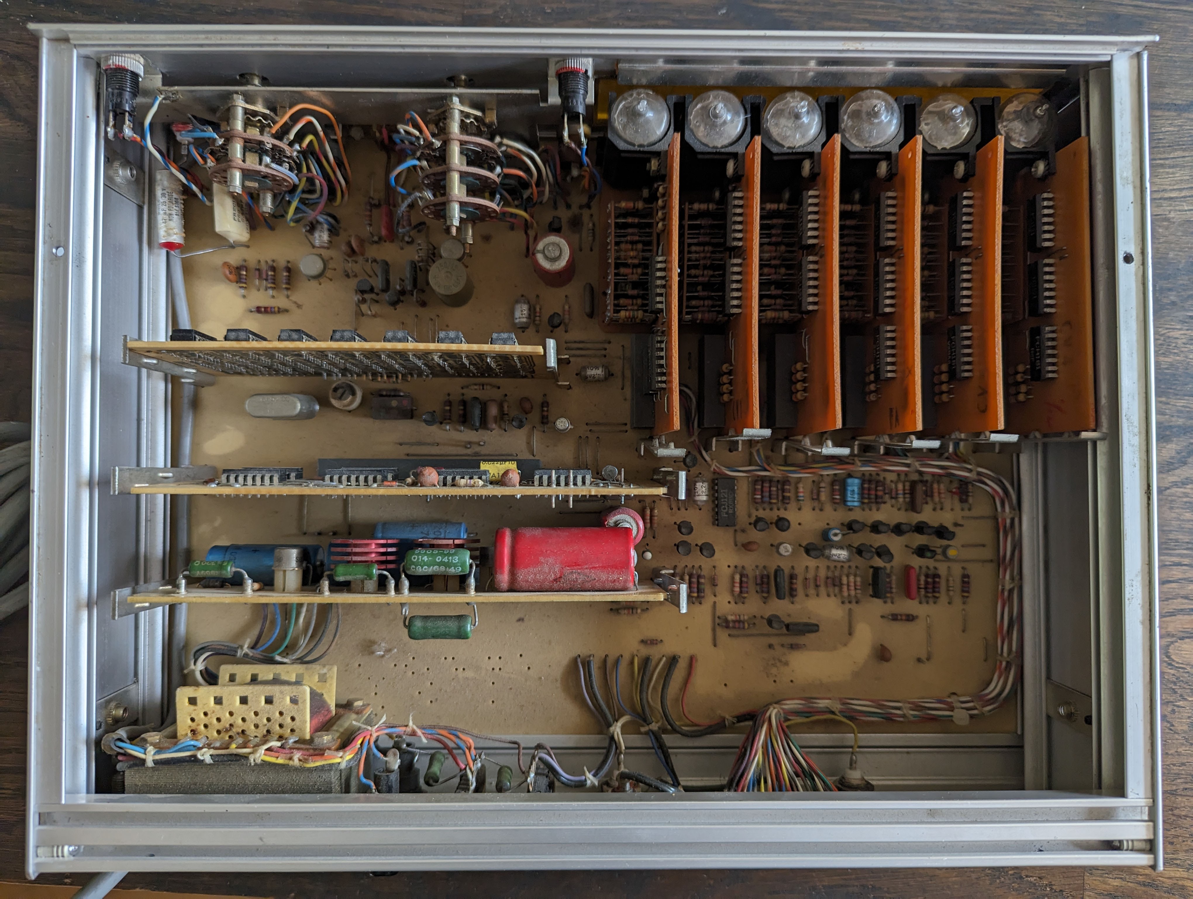
The main PCB board will be kept, as it holds the case together. There are three plug-in modules that will be removed. On it are logic chips (some AND/OR gates and many flip-flops). Looking at the six small boards with the nixies, it becomes clear that these must remain, to hold the nixie tubes in the correct position. I cannot read the part number on the nixies but they seem to be ZM1082's. Looking at the way they are wired, it looks pin-compatible with the ZM1082 at least (pin 13 is the anode).
There are three different types of nixie boards but I think they are compatible. Two of the six boards have an additional little neon tube to act as a dot (see bottom right board in the picture). These, I can probably repurpose for my clock.
The TTL chips use the Mullard numbering (FC series) and seem to be sourced from different manufacturers. There's a few with a date code I can recognise: week 36 of 1972. Half a century of age on this thing!
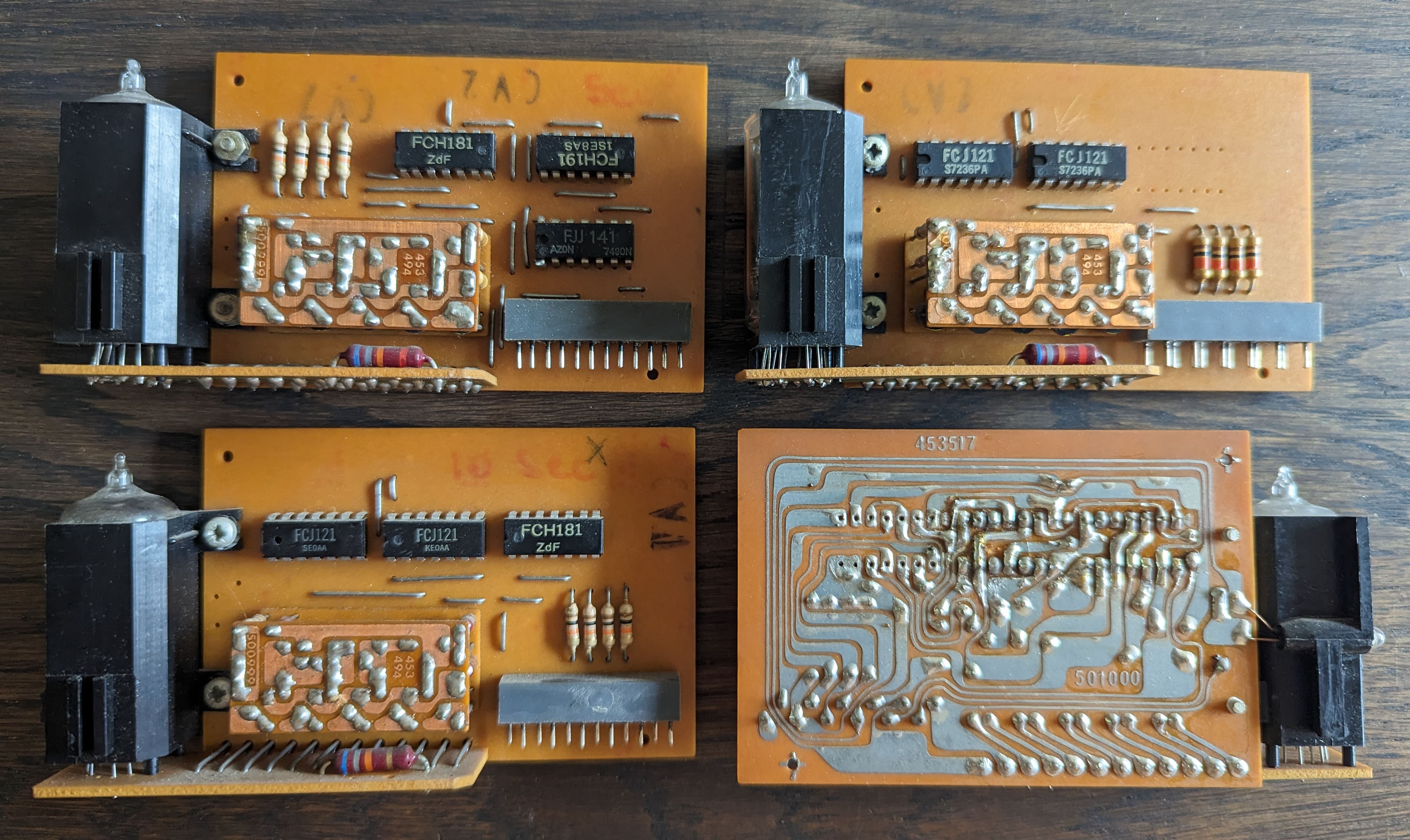
I will cut the traces on the PCB and solder new wires on to just drive the nixie tubes and decouple the rest of the electronics on there.
I want to use a kit for the clock electronics. That needs 12V 1A. I did some testing on the transformer that is in the device, but the voltages are not really suitable. I decided to get a cheap 12V buck converter. Also, I made the decision to not do the build in such a way that you can easily revert to the original device.
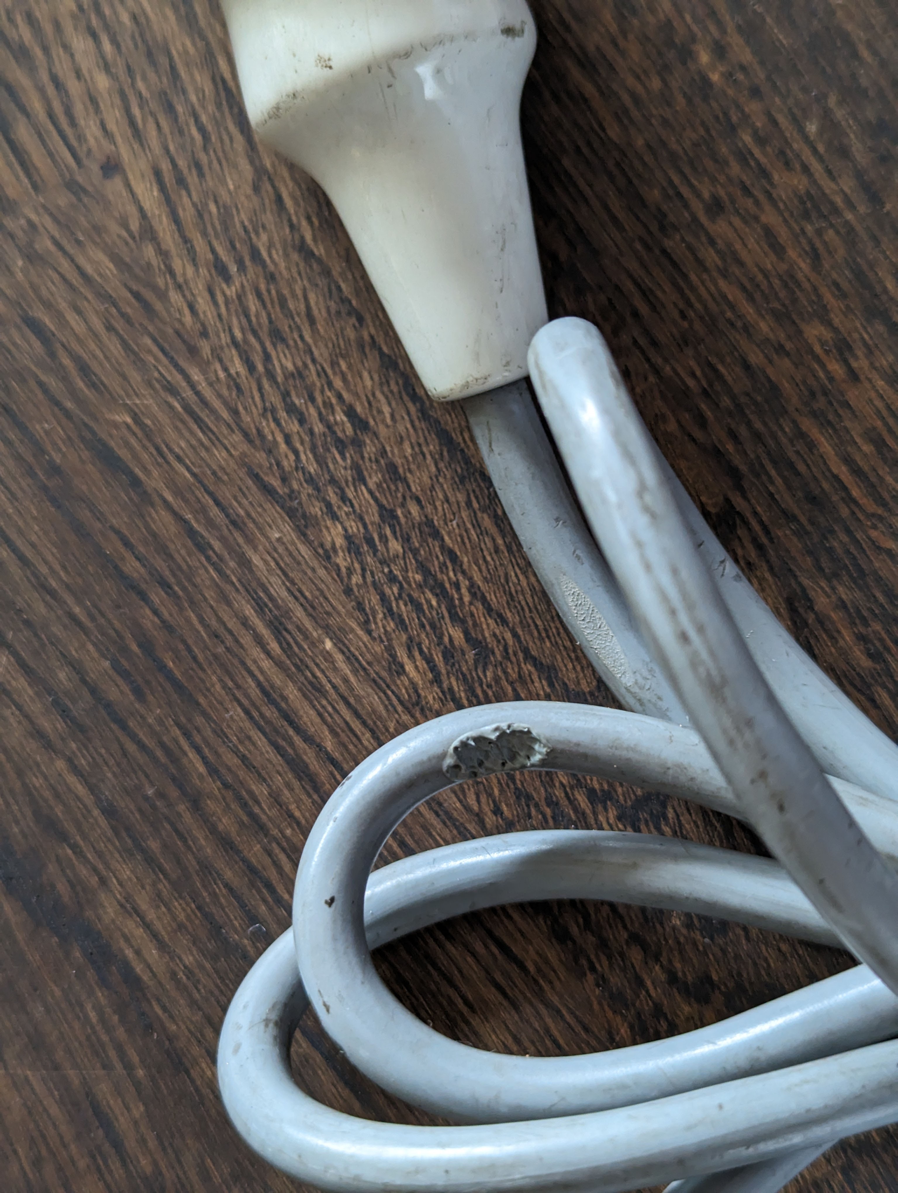
First, the power cable needed to go, as that was damaged.
Then, a look inside the Schneider. In there we see a neat arrangement of components. Some are on the main PCB, but there are also modules that are plugged in to the main PCB. Three of them hold some old logic chips, six are the nixie boards.
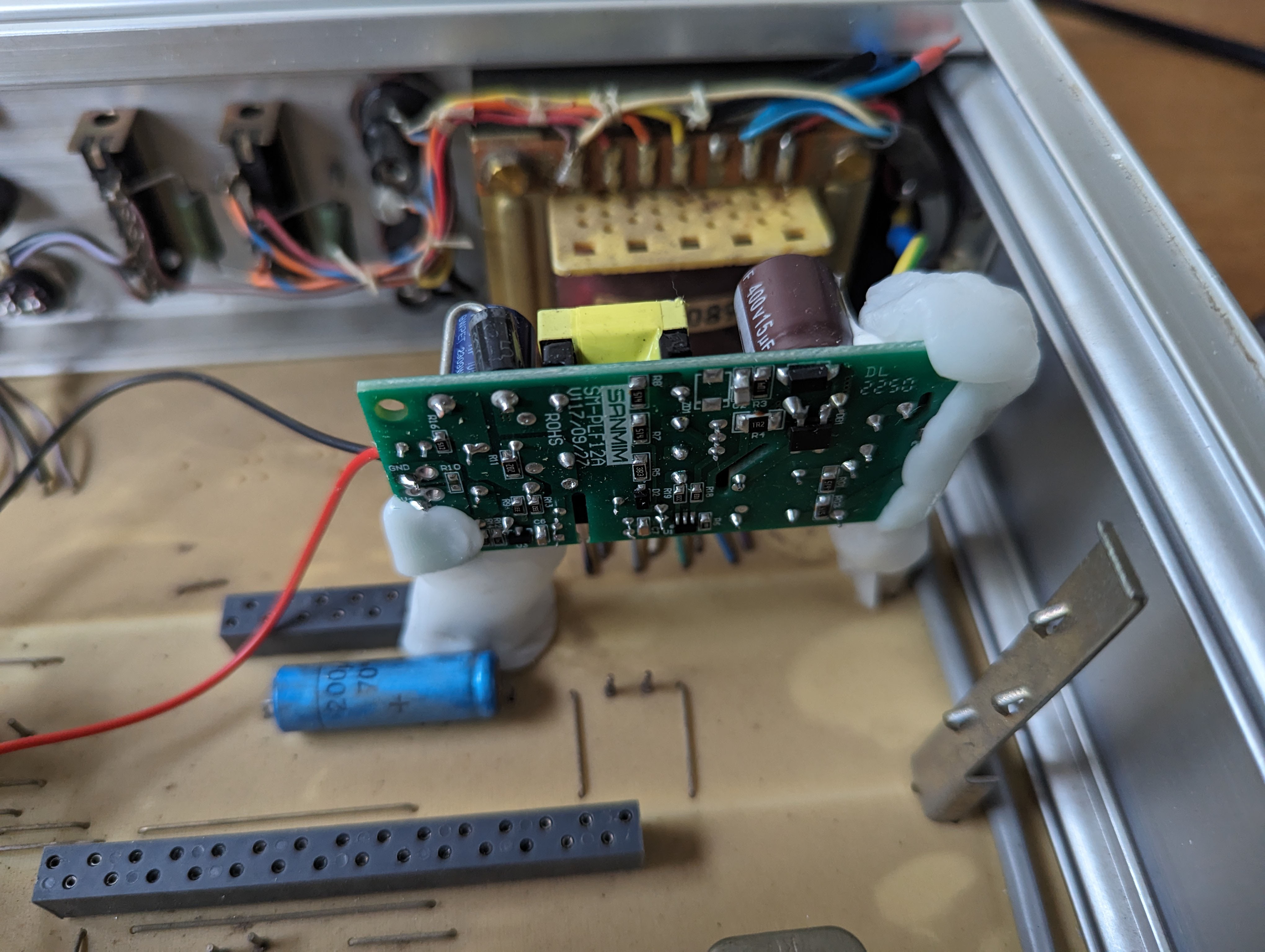
I put in a new power cable, connected ground to the casing, and the mains wires to the buck converter. To securely fix the converter into the enclosure, I again used moldable plastic. The PCB modules have little stands on the side, and I re-used one of those to mount the buck converter upright, away from things that could cause a short.
There's a few things I am contemplating, while waiting for the nixie clock kit to arrive.
- I think of repurposing the display or sensitivity knobs (they are potentiometers with an on/off switch integrated) as main switch, probably the 'display' knob.
- There are 2 lights on the front panel. I could use one to indicate the box is on, but that's not needed as you can see the nixies are on. It would be a shame not to do anything with these lights.. maybe I can use the other knob (the sensitivity knob) to power these lights on or off and set the brightness. The lights seem to be made to run on 9 volts or so.
- I need three push buttons for controlling the clock. I thought about adding three buttons on the back, but I changed my mind and will put 2 on the back (where two BNC connectors currently are) and will use the "reset" switch on the front as the main mode switch.
The enclosure was not very pretty to look at. I used some mild abrasive to clean it up.
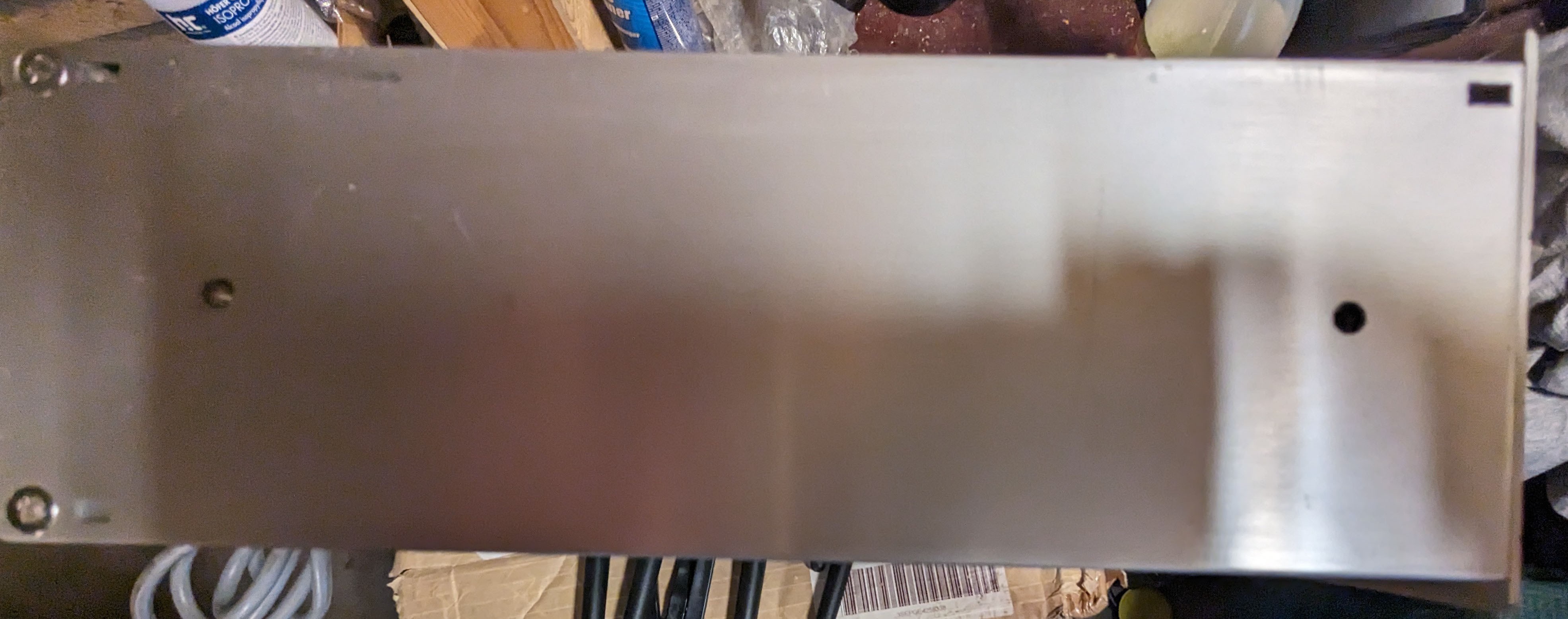
And the side:
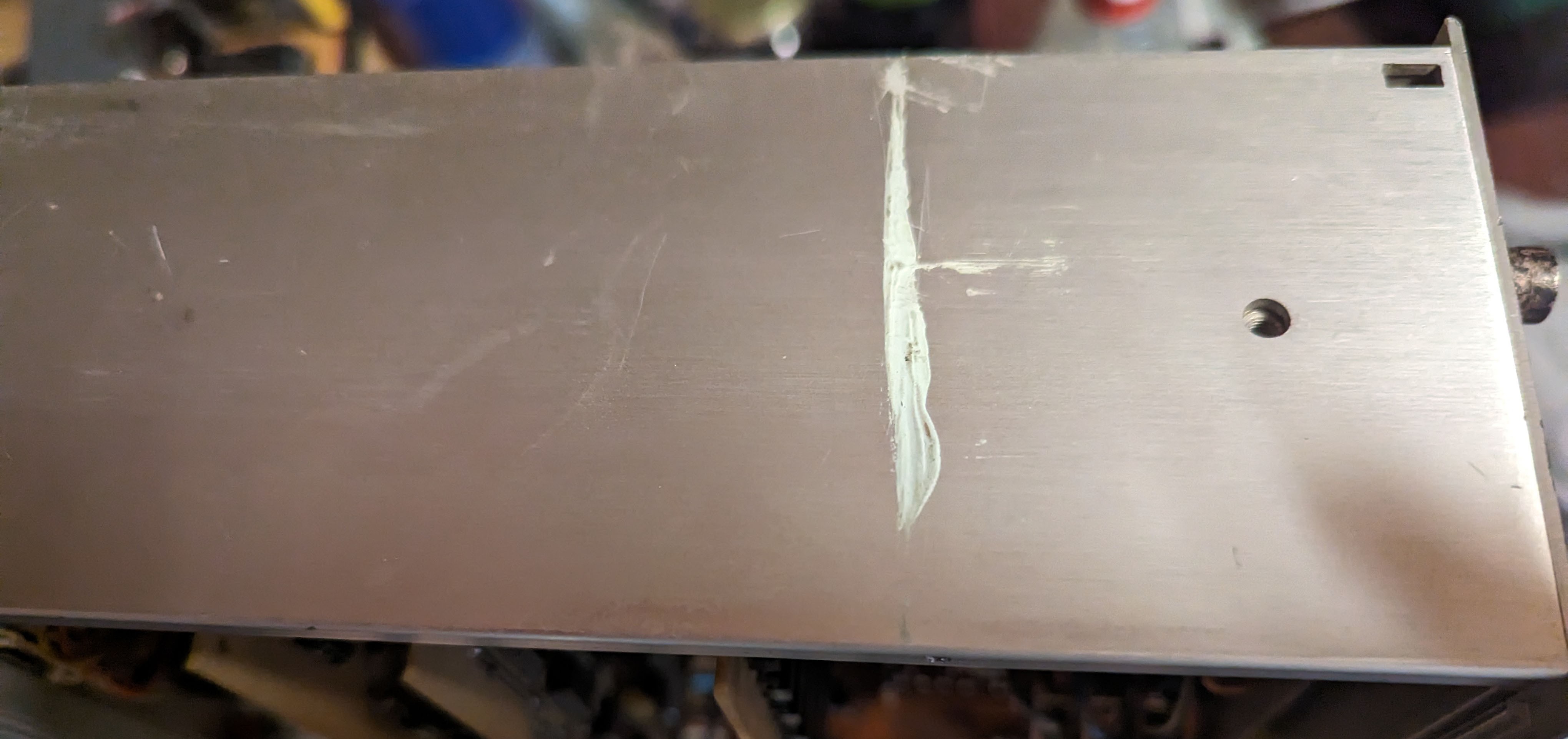
It came out like this:
The "function" knob has a black plastic cover. The other knobs do not. From an eBay advert of a similar system, I've learned that all knobs should have a little cover. I used a bit of moldable plastic that I painted black to make some new ones.
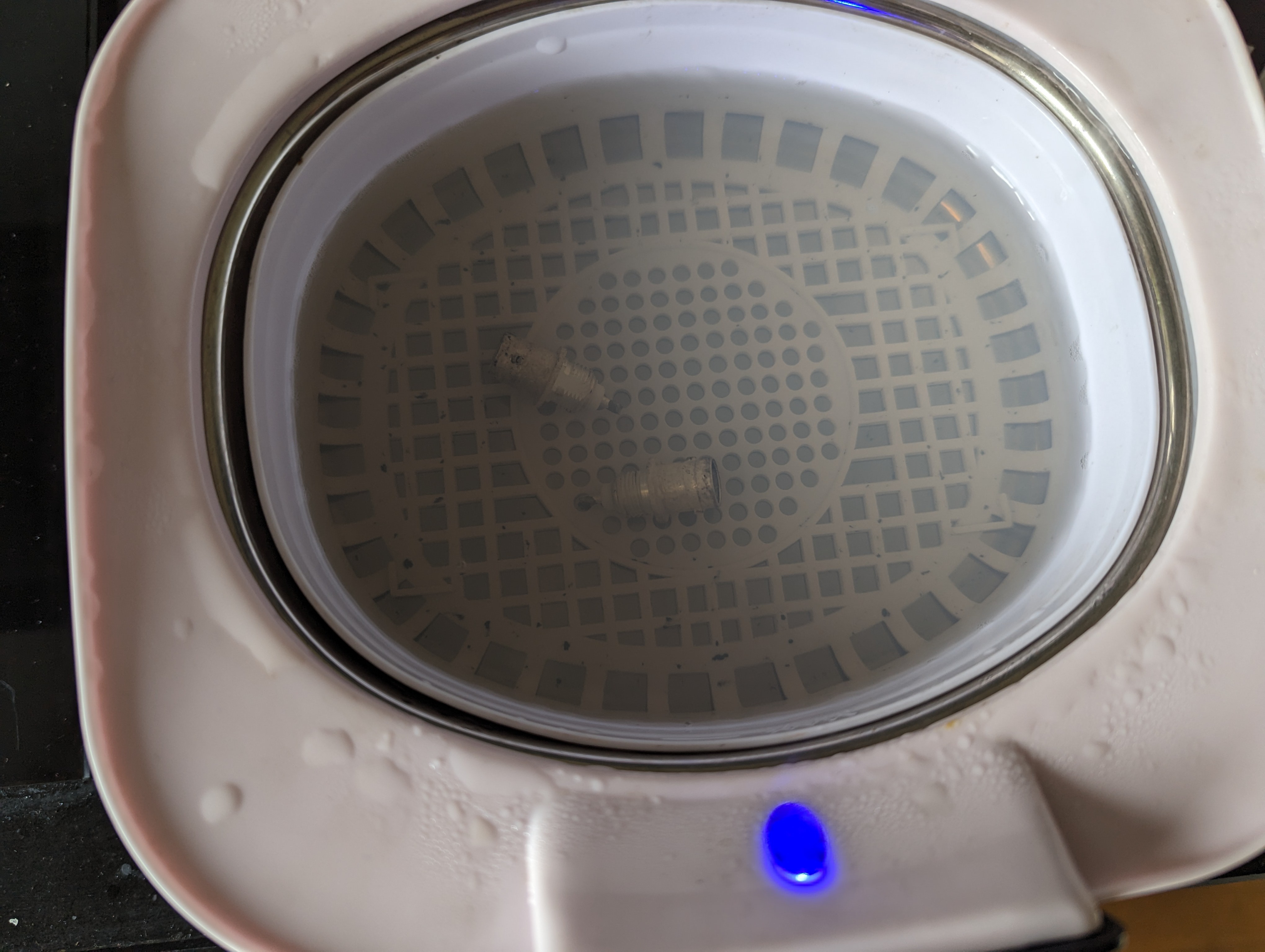
The BNC connectors have turned black. I cleaned them in my little ultrasonic cleaner. Then it dawned on me they were silver! But they cleaned up nicely.
The end result is already a lot better.
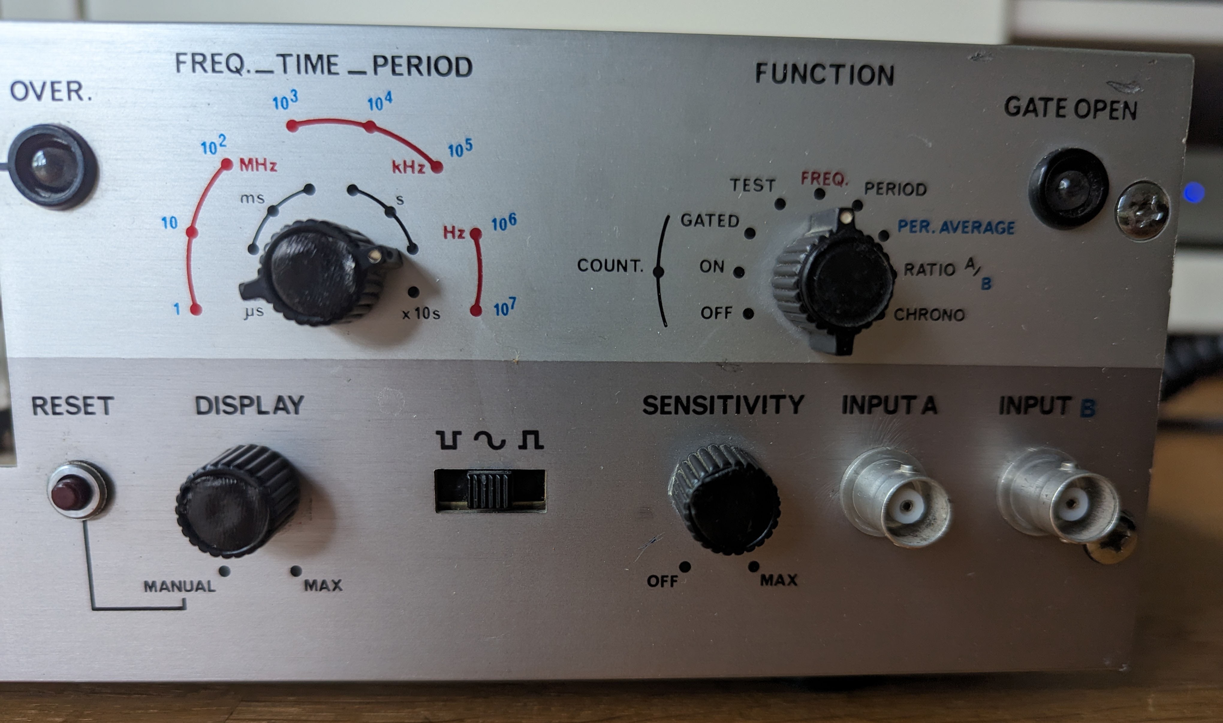
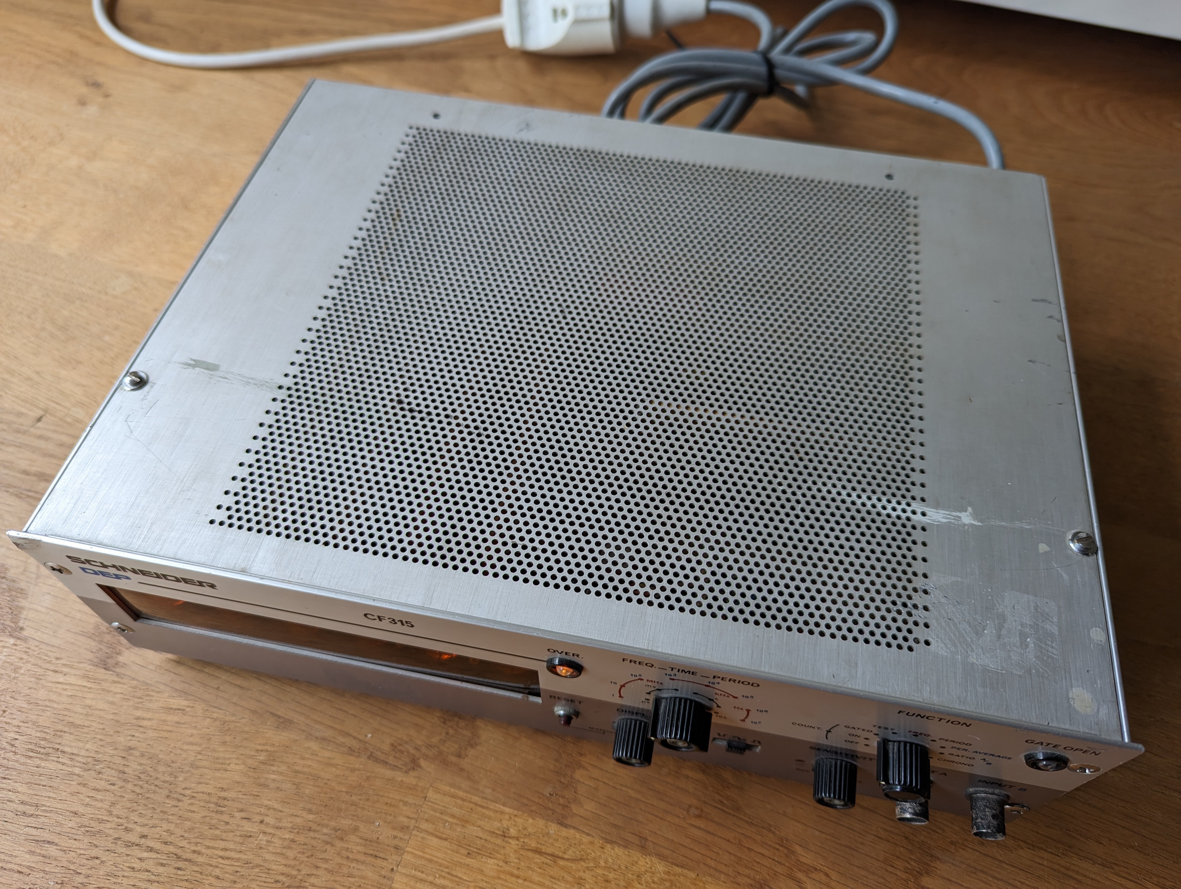
I found an old piece of hardware for sale at a local second hand shop. It's a "Schneider CF315":
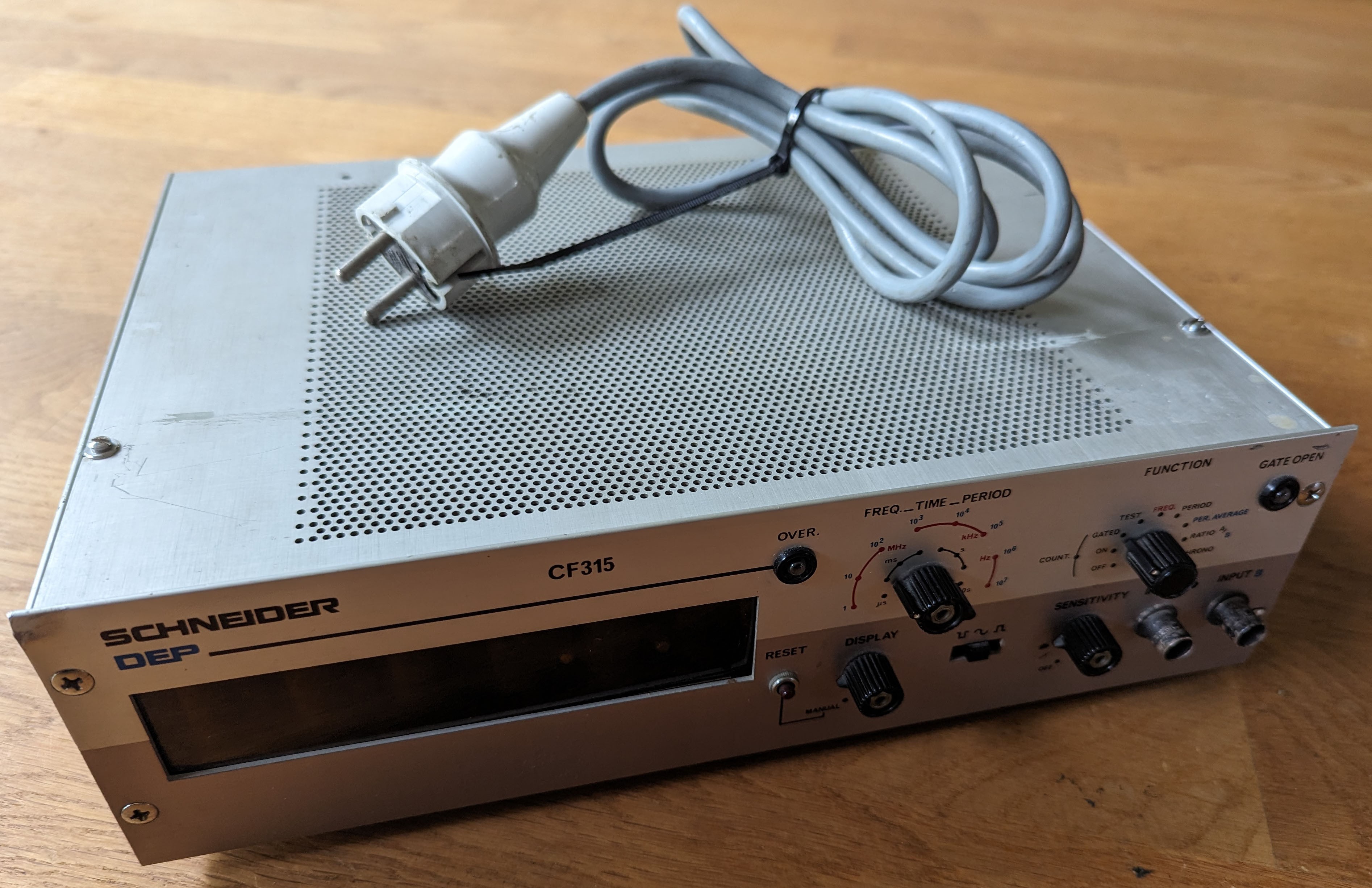
There is not much that can be found online about this device. I did not have a particular use for it, but saw that there were 6 nixie tubes in there. The enclosure looks a bit battered. Some knobs where missing the cover. Otherwise, it seems to be working. I thought of turning this into a nixie clock and bought it.

Create an account to leave a comment. Already have an account? Log In.
Thanks. Always pleased to see those venerable tubes put to use one way or another.
👍 I'd be interested to see what driver circuit is used. I suspect chips from the TTL era. I restored an even older piece of industrial equipment containing nixes in #Repurposing an old nixie thermometer
Become a member to follow this project and never miss any updates
 Gary Marsh
 Tobias
 Spencer
 Pierre-Loup M.
I like your approach where some of the old circuitry is saved. This project is less interesting, as I am basically just building the nixie kit and using the old enclosure. But I like to share it nonetheless.