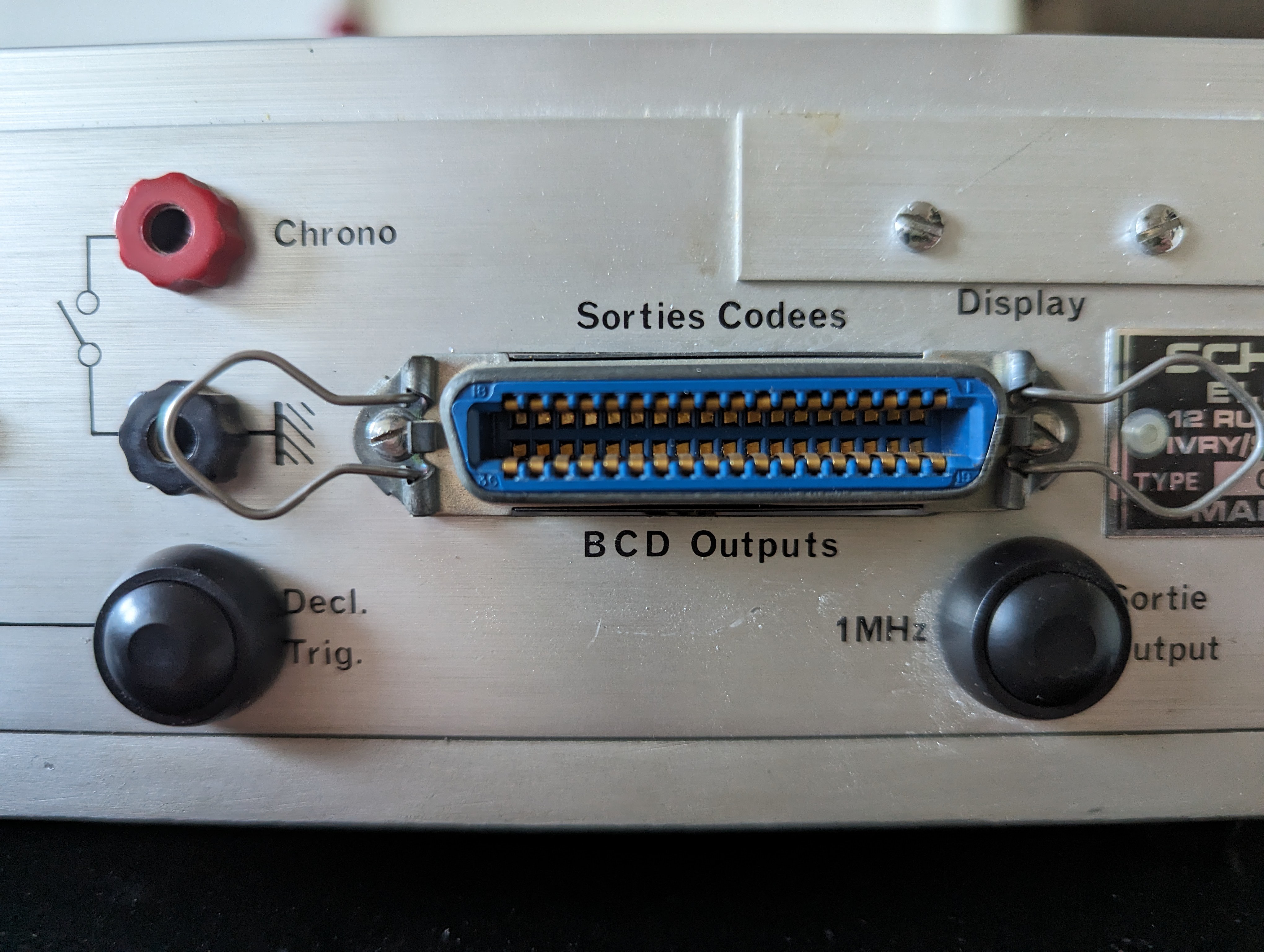
I am still waiting for parts to arrive. But I did a few things. First of all, I took out the BNC connectors at the back and made the holes a bit wider to accomodate two push buttons.

These are used to set and operate the clock. The third button is a button on the front.
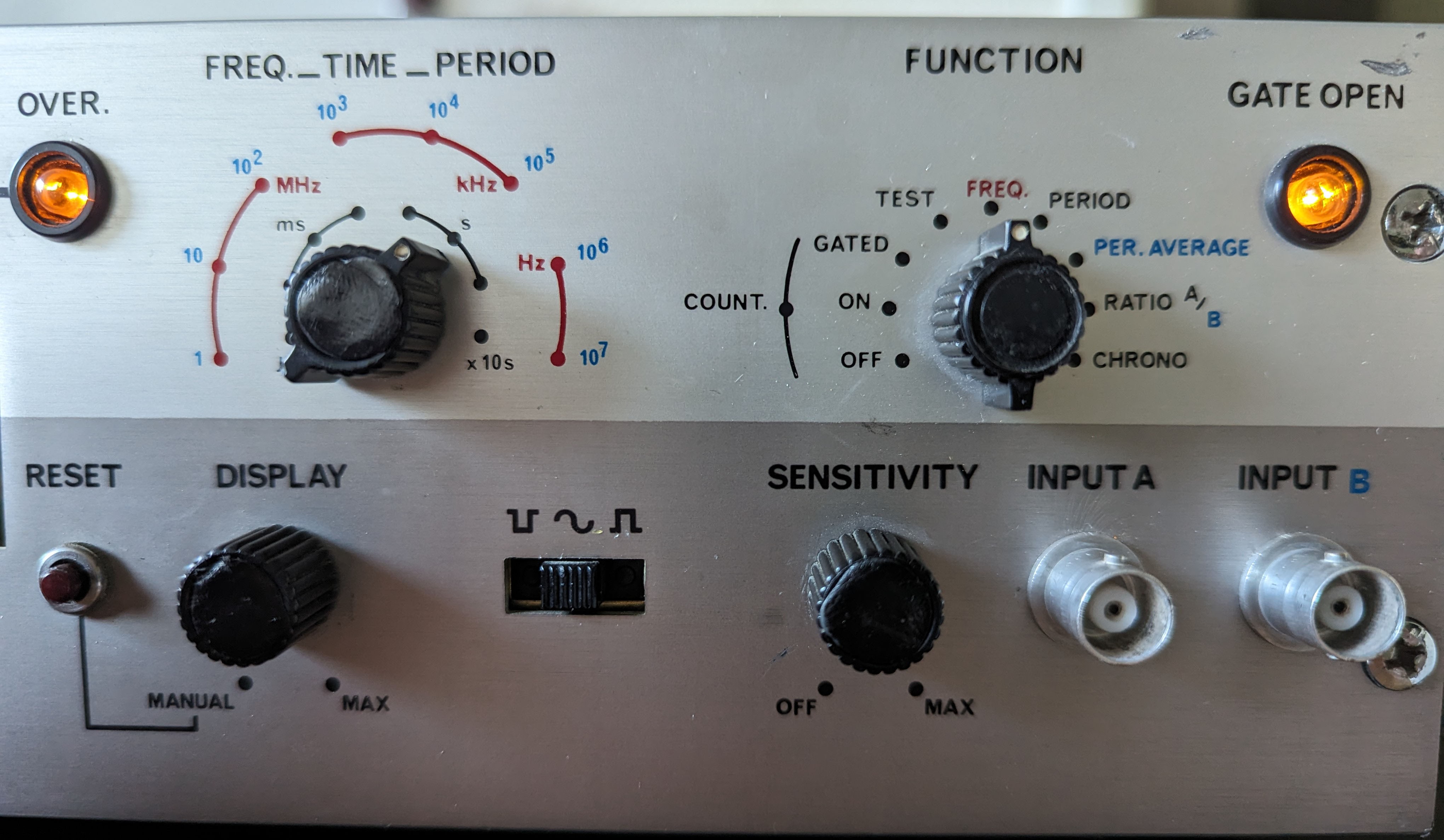
On the front, there are two selector knobs ("display" and "sensitivity") that are on/off switches with a potentiometer in one. The left one, marked "display", I wired to be the main on/off switch. The potentiometer is not used.
The "sensitivity" knob now turns the light(s) on/off. The potentiometer is used to set the brightness. Unfortunately, the potentiometer is in the MOhm range, so there is very limited movement until the power drops below the light being visible. I also added a resistor to dim the light a bit, as I worry it will burn if left on 12V for too long.
Since there are two lights, I also repurposed the switch to select up or down flank. This switch has three positions. In the left, the left light goes on, in the right the right, and by adding a few diodes now both lights light up when it's in the middle position.

 Walter
Discussions
Become a Hackaday.io Member
Create an account to leave a comment. Already have an account? Log In.