Step 1: Power Amplifier Conceptual Framework
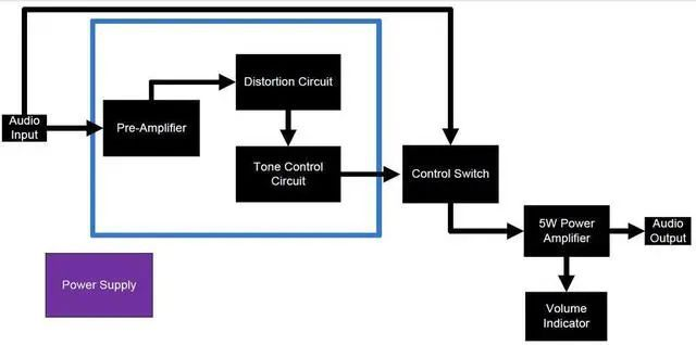
Audio In - 1/4" jack input, here we plugged in an instrument audio signal
Preamplifier - Audio filter and signal amplification that amplifies the input signal before it reaches the power amplifier stage.
Distortion Circuit - A circuit based on a simple diode clamp, since we have a gain option in the preamplifier stage, we can adjust the gain of the clipped signal.
Tone Control Circuit - Simple bandpass filter that changes the characteristics of the output frequency.
Control Switch - Used to select the audio input path that will go to the power amplifier circuit. One of: The input signal through the instrument or the signal processed by the preamplifier.
5W Power Amplifier - Audio Power Amplifier Circuit, designed in bridge load mode. We have two 2.5W LM380 ICs that can be doubled in bridge form.
Volume Indicator - Comparator based circuit designed with a basic peak detector, 4 comparators and 4 outputs, connected to front panel LEDs.
Audio output - 1/4" jack differential output, please note that there is no ground grid on the output. Here we connect 4-8 ohm speakers, but not more than 5W.
Step 2: Parts and Instruments
Complete List of Everything You Need: Parts
A. Common parts:
1.5mm diameter wire
Plastic case - I used a 100x150mm plastic case. Make sure it is easy to drill.
0.3mm wire - for electrical connection.
1 x prototyping board - preferably single sided, easy to desolder if there is a soldering error.
16 x Shrink Tubing - Protect unshielded wires.
3 slider potentiometer knobs.
4 x metal screws - box enclosure
14-18V DC power supply, 0.9A or higher.
B. Front panel assembly:
1 x SPDT switch
2 x SPST switches.
2 x 1/4" phone jack - guitar in\speaker out.
3 green LEDs.
2 red LEDs.
1 x Power jack - 15V power input.
8 x Label Stickers - Add instructions on your device.
C. Electrical parts:
1. Resistance:
2 x 1M
12 x 10K
5 x 1K
1 x 220K
1 x 100K
2 x 470K
1 x 10R-power resistor
1 x 2K2
2. Capacitor: 2.1 Non-polarized:
1 x 1n
1 x 10n
1 x 50n
1 x 50p
1 x 22n
1 x 470n
1 x 100p
1 x 100n
2.2 Polarized:
2 x 10u
3 x 330u
3. IC and other parts:
1 x LM7812-12V linear regulator.
2 x LM380-Audio 2.5W Power Amplifier.
2 x LM324 - low power quad operational amplifier.
1 x LM741 - general purpose operational amplifier.
1 x 1N4007 - general purpose diode.
2 x 1N5817 - signal diodes
3 x 100K slider potentiometers - can be rotated - no difference.
Step 3: Schematic - How the Device Works
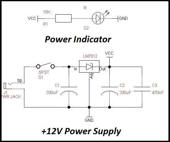
The schematic is very simple:
The switch "throw" pin is connected to the potentiometer, its opposite pin is connected to ground, and the wiper pin is connected to the LM380 IC input. Note that the 100K potentiometer will be used as a volume control. The LM380 IC is connected in bridge-tied load mode.
Both ICs amplify sound signals with small amplitudes, but the second LM380 acts as an inverting amplifier - so at the output of both ICs we get an amplified signal that is larger, but with opposite polarity. By connecting a load to these outputs, the differential voltage across the load is doubled and therefore the maximum power at the load is doubled. prove:
P(differential)=2*V*I=2*P(single)=2*2.5=5W
The differential output (J3 symbol on the schematic) is the audio output of the amplifier. I used a 1/4" phono jack, so I just connected the output speakers directly to the amp.
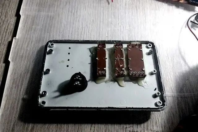
Step 4: Soldering
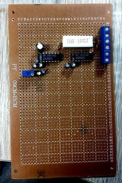
Soldering is the most fun part of building, especially audio circuits.
First, it is critical to carefully consider the soldering process and determine where the components will be placed. It was much easier for me to break the whole circuit up into groups and solder them part by part:
Power Amp > Preamp > Volume Control > Power Supply > Terminal Blocks > Cut Circuit Board.
Let's describe the steps:
1. LM380 Power Amplifier Circuit: This is the last but not least in the schematic, but the part I soldered first.
Important: Leave some space for the output filter resistors. Its geometric volume is much larger than other resistors in the circuit.
2. Pre-amplifier circuit: The circuit with the largest number of components in the project.
3. Volume Control Circuit: Since we only have a single IC for the quad op-amp, it's easy to imagine where each component should be placed during this step. The front panel has LEDs, so a breakout board throughput is required to solder each LED (next section will show how to connect the front panel with the board). The voltage bias supply (4.5V, see section U4A of the schematic) is connected to U2 (voltage comparator), so don't forget to make the connection between the two ICs.
4. Power: The last circuit that will appear on the board. I didn't solder it initially - I just soldered two wires to the power pins (VCC and GND) and powered from an external source to check the initial working of the amp. Bypass capacitors should be placed close to the LM7812 IC.
5. Terminal block: the interface between the front and rear panels and the new soldering board. TB should be soldered close to the desired board area. After soldering all the connecting wires, it is recommended to draw the TB connection diagram.
Step 5: Making the Box
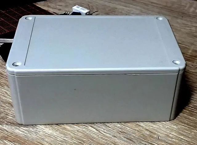
Preparing the case enclosure was a difficult process for me. Before doing any cutting work, make sure your circuit will fit within the volume of your cabinet, for cables and interconnects - a lot. First, mark the area that will be cut, I highly recommend drawing a "cross" on each hole area, this will be the drill reference for each cut. Drill list: 1. 2 x round 1/4" audio I/O holes 2. 2 x round SPST switch holes 3. 4 x round LED volume indicator holes 4. 1 x round LED power indicator holes 5. 1 x circular SPDT switch hole 6. 3 x rectangular slider potentiometer cutout area 7. 1 x rectangular power socket input hole
Step 6: Assembly
This is the final step of our project, all the hard work has been done.
Front Panel: Contains 3 slider potentiometers and 4 LEDs for volume indicator and "distortion on/off" switch.
Potentiometer - must be placed in a fixed position, once placed, the potentiometer should be glued on with hot glue.
Distortion On/Off Switch - I used my own side plastic clip so no need to hot glue it. Insert should be enough.
LEDs - Before proceeding to place them on the front panel, we have to prepare: solder colored wires and mask. Solder the black wire to the negative side of each LED and the red wire to the positive side of each LED. After soldering, place shrink tubing over all solder points and heat with a hair dryer or lighter.
Rear panel: Contains the power connector, 1/4" female audio I/O connector, power indicator light and power on/off switch.
Power connectors - round connectors are highly recommended - no need to sharpen the socket. With the slots behind the rear panel prepared, hot glue the connectors.
1/4" Audio I/O Interface - Once the appropriate diameter hole is machined, plug in the connector.
Power On Indicator - LED should go through the same steps as the front panel LED.
Power On/Off Switch - Same type as the switch on the front panel.
Wires: After everything is done, wires need to be soldered to the front/rear panels
Label stickers: To make it look cooler, I added labels to each element on both panels
Knobs: Designed to include slider knobs
Speaker set: Since the output signal comes from a 1/4" female jack connector, I soldered 1/4" male jacks to the speaker wires
Step 7: Test
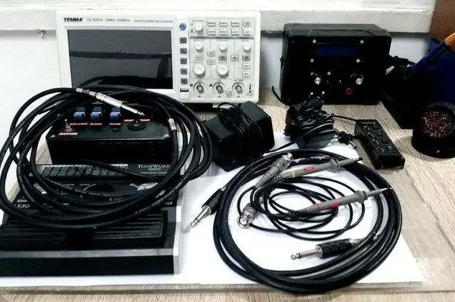
Input: The audio input is connected to the function generator, the audio range is 20Hz-20KHz. The sine wave amplitude ranges from 20mV to 700mV.
Power Supply: If you don't want to use a DC adapter, an external power supply with a DC current indication can be very useful during the test procedure.
Output: The audio output is connected to an 8 Ohm speaker with a minimum power rating of 5W.