 Guyrandy Jean-Gilles
Paying Bills
PCBWay graciously offered to sponsor this revision of the board. With them I've had the flexibility to source parts from multiple trusted sources. They are also quite thorough with their file approval process to avoid any surprises once boards ship. Thanks PCBWay!
Update
I've avoided adding a battery solution since I wanted to focus on prototyping the e-reader features. The previous version of hardware and software had the minimal feature set an e-reader requires, so I finally bit the bullet and implemented portable power. I decided not to implement power on the HAT version of the hardware as that's uncommon for that form factor. I consider that version of the hardware done with buttons as inputs. Once I have touchscreens, I'll do a revision of the HAT.
With respect to portable power, my goal was to keep the device as thin as possible which effectively required a lithium polymer battery. Sparkfun sells a 1250 mAh lipo battery that perfectly fits the carrier board.
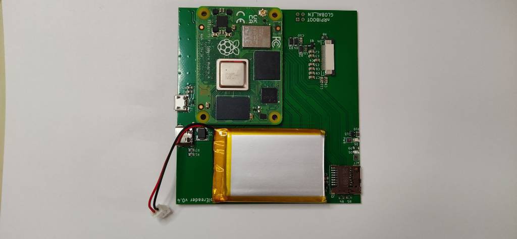
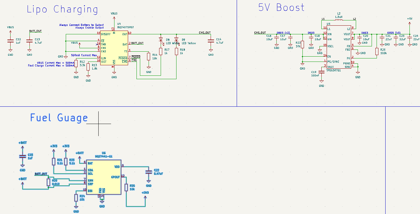
I also lifted the design of Sparkfun's battery babysitter and their buck-boost converter to create the charging circuit, 5V regulation, and battery status monitoring. TI's BQ24075 charges the battery and has built in protection circuitry. TI's BQ27441-G1 monitors the battery's charging status, amount other things, and communicates via I2C. Finally, I'm using TI's TPS63701 as a fixed 5V voltage boost converter.
If I was pulling the max 1.5 A out of a USB C connector I might've gone with a 4 layer design or at least 2 oz copper, but I'll stick with 2 layers and 1 oz copper because I think I can get away with it. Below is the updated layout followed by the previous version's layout.
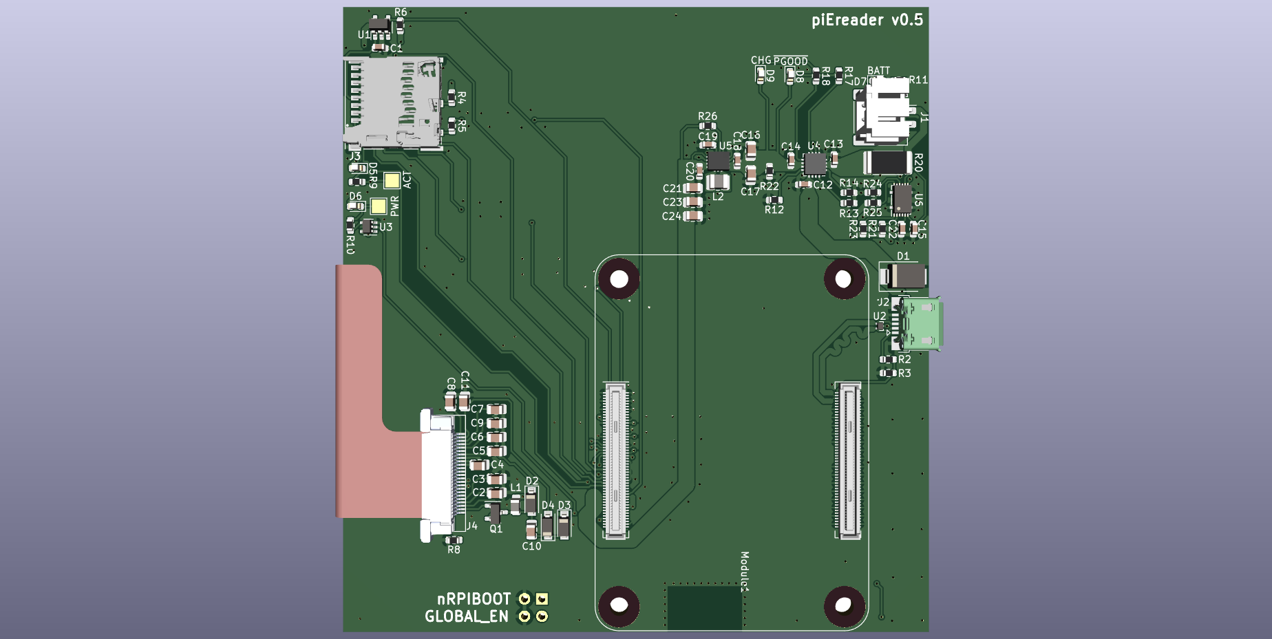
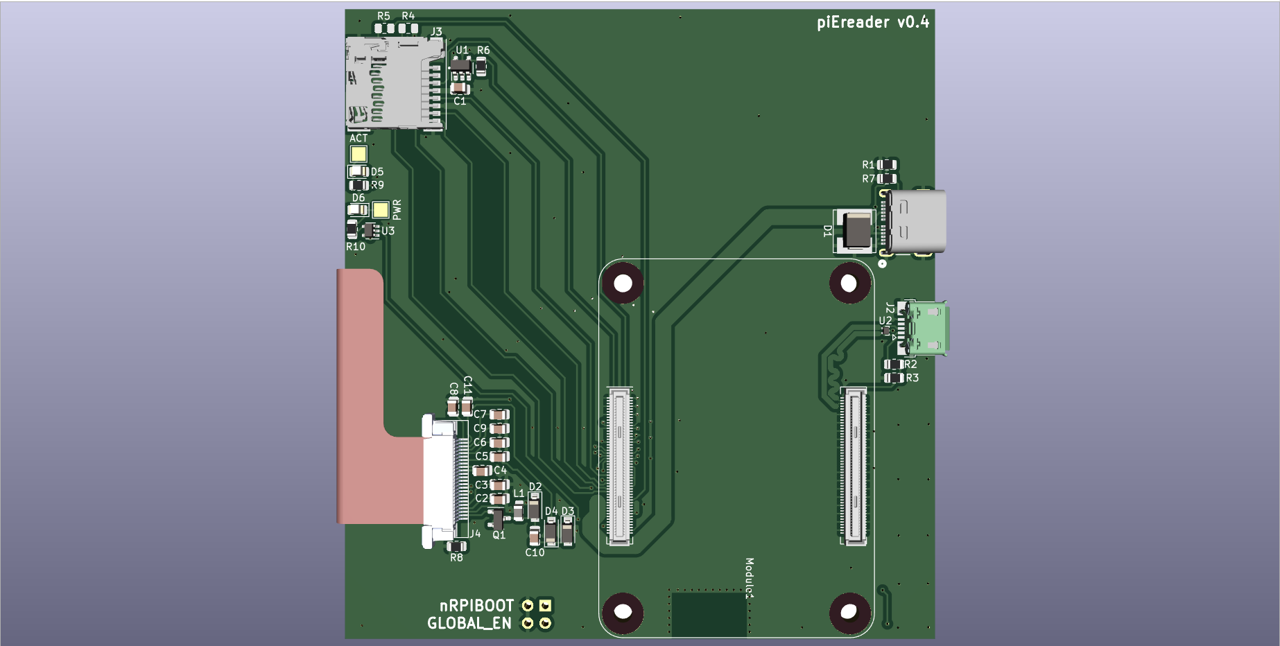
Notice that the newest version has only one USB connector. Also notice that the SD card connector flipped 180 degrees because I routed it incorrectly last version. Remember, I don't have any CM4 Lite modules to test the SD card circuitry so I don't have a way to validate that part of the hardware.
We'll see if there are any hardware bugs when I get the boards from PCBWay. For more details on the design and most up-to-date status, check the project's Gitlab repository.
Discussions
Become a Hackaday.io Member
Create an account to leave a comment. Already have an account? Log In.