 Dominic Emond-Belanger
Hello, It's time for an update on my 80286 project!
I began to work on my 1st motherboard PCB prototype in the past month since working on a breadboard is becoming too challenging.
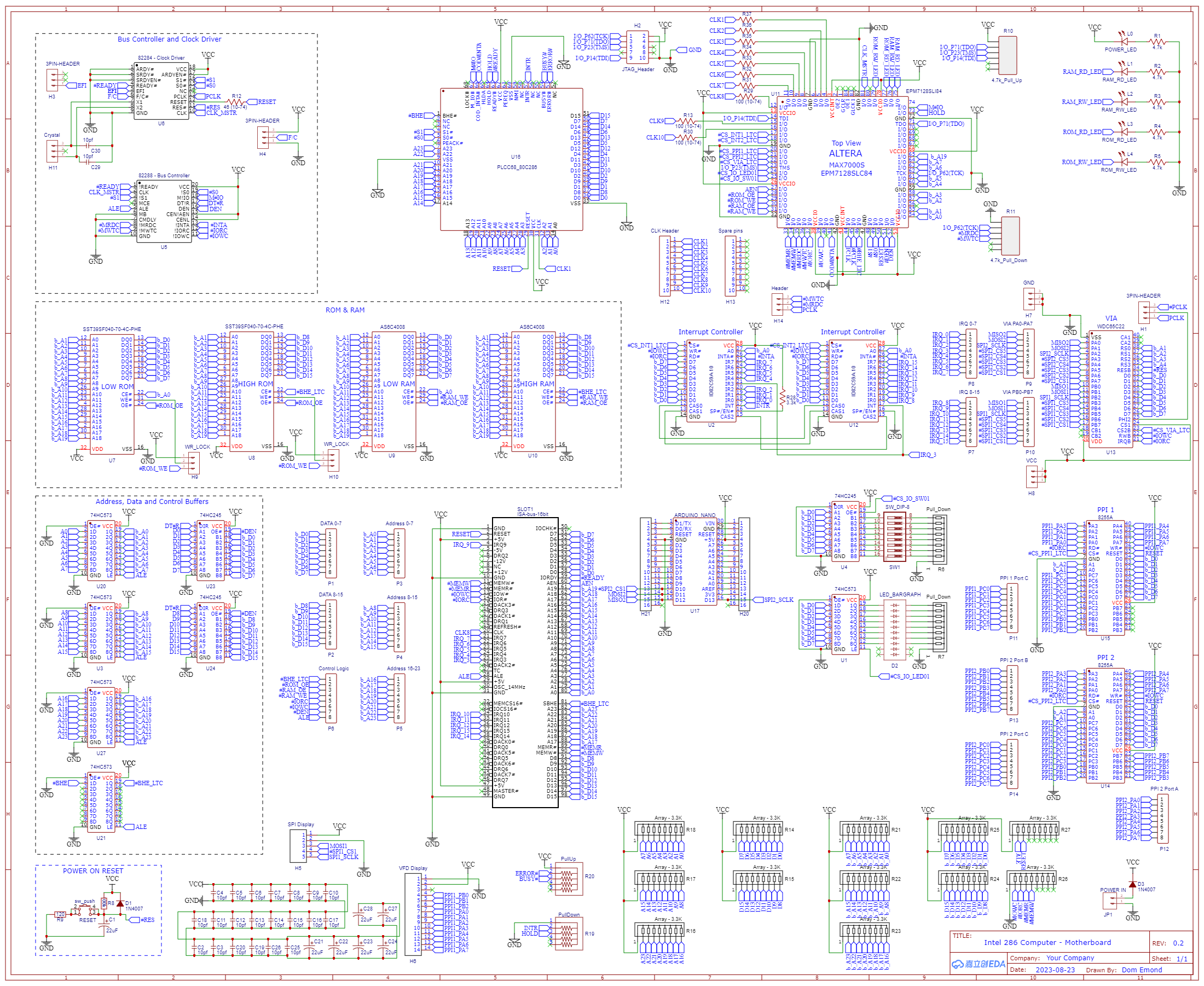
The goal of this version is to consolidate everything that is working on my breadboard version to a cleaner setup but let me add new things on top. I had also added a ISA port to plug a ISA debug card with the Arduino Mega for debuging.
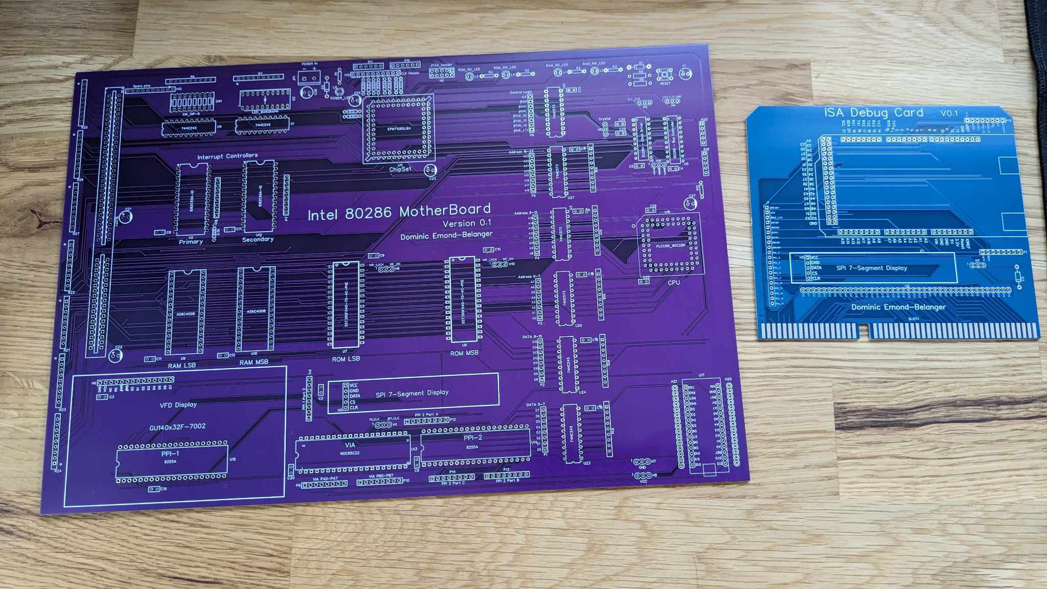
Here's the final result after receiving the produced boards :
The first test run :
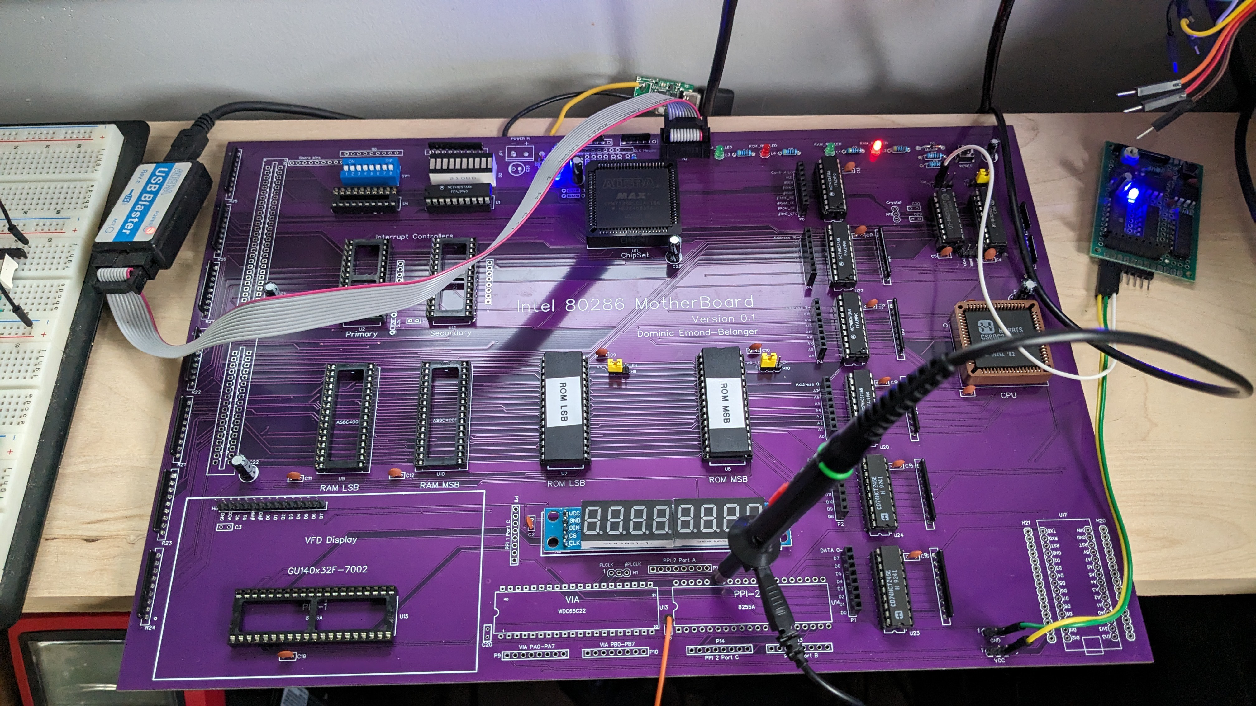
When testing the board I accidentally burned my 82C284 Clock Driver chip, luckily I was able to make a replacement with a GAL chip on a little protoboard.
And here's the first run I did with the debug card installed to troubleshoot the PPI :
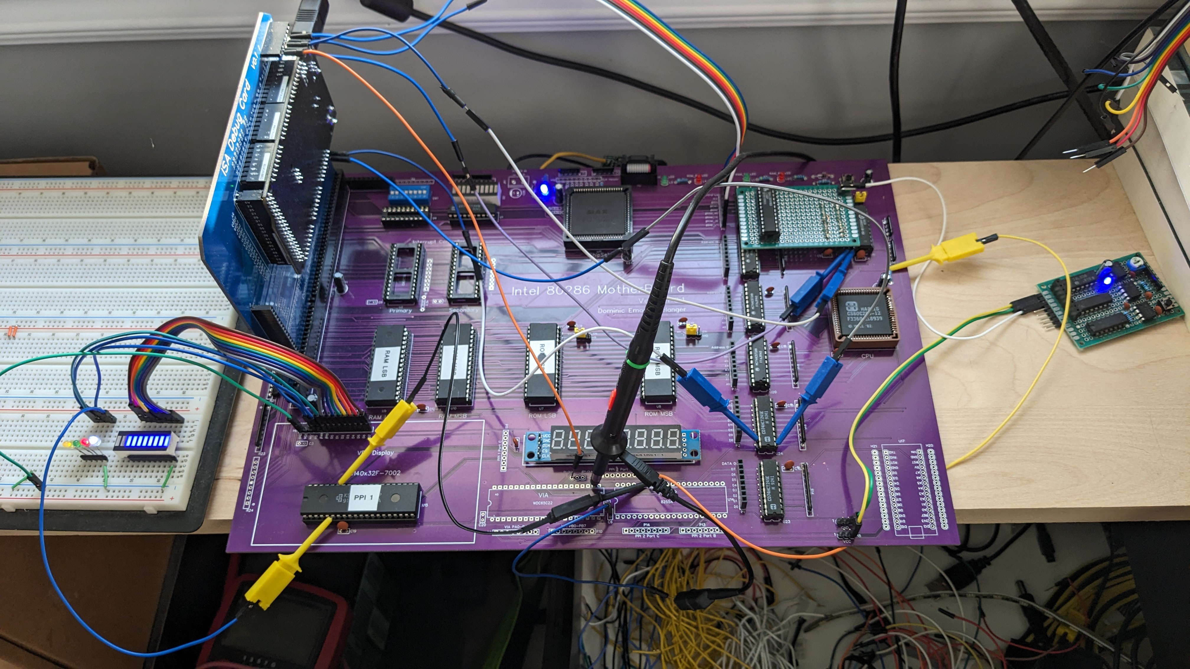
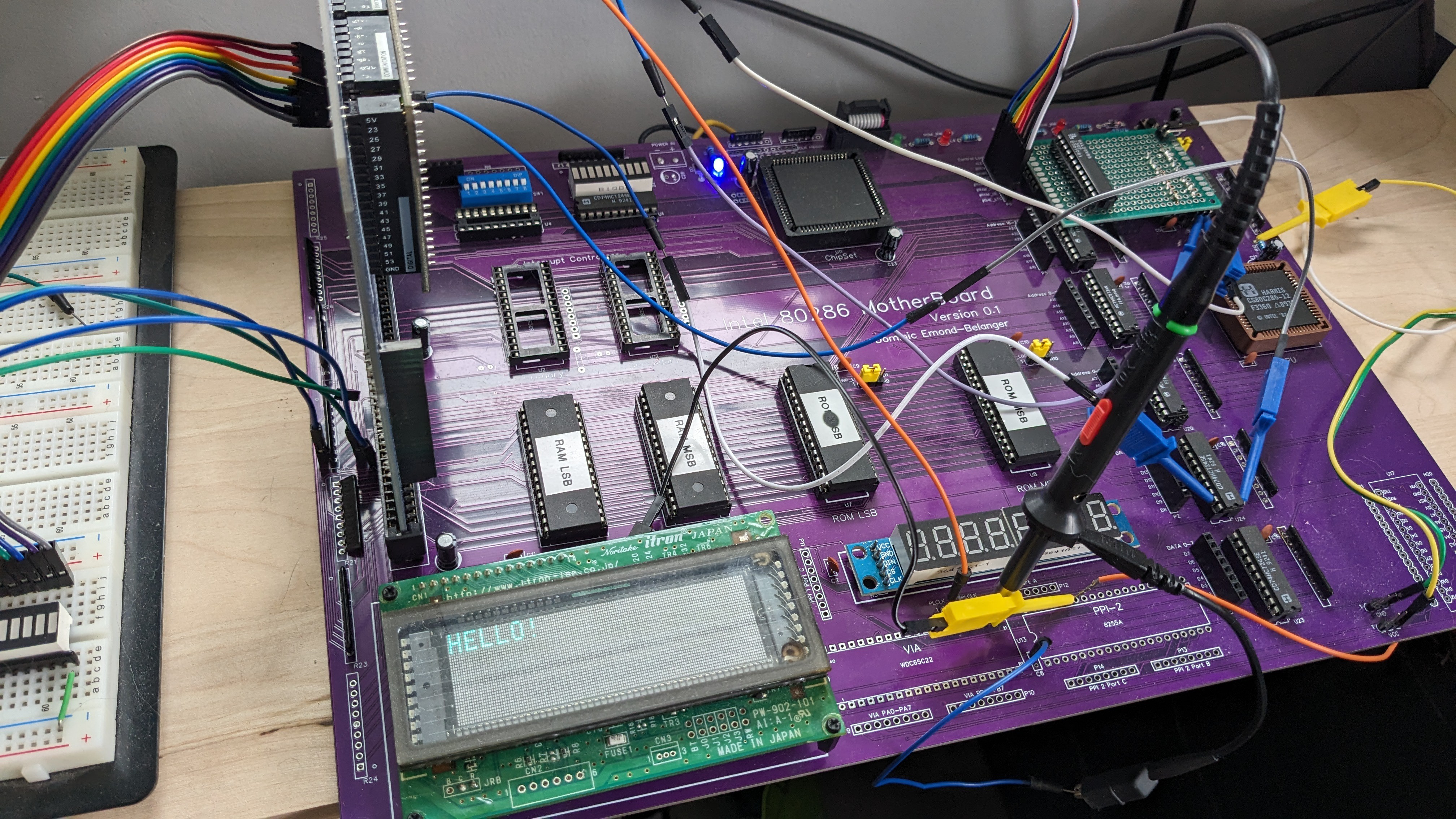
Finally after a week of troubleshooting, a lot of cut traces and bodge wires, I was able to make my VFD screen work again thru the PPI :
The next step will be to use this platform to learn more about x86 assembly and begin work on a BIOS.
Until next time...
Dom
Discussions
Become a Hackaday.io Member
Create an account to leave a comment. Already have an account? Log In.