 Keith
Keith2026-01-10
Looking at the ZX81+38 video buffer, it seems to have puzzling faults.
When active, the impedance is two 100R resistors in parallel, making 50R. Again, wrong. Two 150R resistors might fix that, but I suspect this is not the correct way to do it. I expected a low-Z buffer with a 75R series resistor to the output socket.
SYNC low shuts off all base current, and the resistors do not present a 75R impedance. Just a 100R to ground. The designer specified a Schottky diode to ensure the base voltage goes lower than the transistor's switch-on voltage.
In practice, you have to have the transistor conducting a bit, to keep it low-impedance. You add a DC offset small enough to be seen as 0V by the monitor.
R48 and 49 are 470 and 1000 ohms, so V_base = 1.6 or 5 volts. Less V_be of 0.7 volts, V_emitter = 0.9 or 4.3 volts. The 0.9 volts is halved to 0.45 at the socket, but 4.3 becomes 2.15. This is 1.7 volts video range.
A proper video signal has 0.3 volt sync depth, and 0.7 volt picture signal depth.
After looking at how others had done this 1-transistor solution, I concluded that none of them were well designed at all. Atari were notoriously bad at this. I expected better of Acorn, but some of their circuits don't stand up to analysis or have potentiometers for the user to twiddle for best results.
So I had a go at designing my own, working back from the proper standard video levels.
Here is my first go:
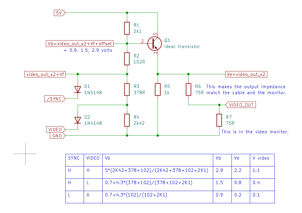
It assumes an ideal transistor, with infinite gain and zero R_base_emitter, and that the V_base_emitter and diode V_forward are 0.7 volts.
I started with biasing the transistor for white level, then sync level, then black level.
Sync low overrides the video_in level. As you can see, I deliberately used a PIN diode for D1 so the base is biased to conduction (0.7) and resistor R2 adds 0.2V to make the sync level 0.1 volts at the monitor.
D2 also adds 0.7 volts, R2+R3 = 480R to set the black level output.
When Sync is high and video is high, R1...4 set the white level output.
The ideal resistor values soon got off the E24 series, and I don't have the time to work out the best way to improve the values. Especially because the actual resistors will diverge from ideal when dealing with real (non-ideal) transistors and diodes.
I had a second attempt using diodes to control the base voltage. Diodes are more expensive than resistors but my time is more expensive than it is worth to find the best resistor combinations.
It uses 1 more diode, 2 fewer resistors and the resistors are all E24:

This makes use of the fact that PIN diodes have V_f about the same as the video picture depth range, i.e. 0.7 volts. D1 counters V_be, D2 adds an output bias voltage, and D3 adds 0.35 volts sync depth (a tad over the official 0.3 volts).
In the real world, the transistor has a non-zero R_be, which should be subtracted from R4. This is why you often see resistors less than 75R in this position in similar emitter-follower circuits. Typically 68R.
R_base_emitter = V_thermal / I_collector
where
- V_thermal is approximately 25mV to 26mV at room temperature (around 25°C).
- I_collector is the quiescent DC collector current of the transistor (in this design
In this circuit, the latter is 17.63 mA so R_base_emitter is about 1.45 R. so R4 of 75R is close enough.
Diode V_f and transistor V_be vary with current and temperature. Check data sheets to make sure they have the right current flowing through them to get 0.7 volts V_f. This looks to be about 3mA at 20C. That would need R1 to be (5-0.9)/0.003 = 1367R and thus R2 = 2050R. The nearest E24 values of
1300 and 2000 set V_white = 1.165 volts.
1500 and 2200 set V_white to 1.136 volts.
1000 and 1500 set V_white to 1.15, with 2mA during white output.
During black output, R2 steals some current from the diodes, so 3.4mA flows in R1 and 1.07 ma through R3, meaning 2.33 mA flows through the diodes.
In practice, most monitors are forgiving, and usually manage to cope with imperfect video signals. The human eye can cope too, and there is a brightness control you can adjust.
A bonus of this circuit is that it should work the same with sync and video in from TTL and CMOS chips, which differ in their V_high voltages.
2026-01-12
I breadboarded this circuit to observe its behaviour. I did not have a Schottky diode, so I used a PIN diode instead. I expected this to raise the black and sync levels by 0.5 volts. With the diodes disconnected, V_out = 1.116. Black and Sync are 585 and 305 mV, which are about 0.135 and 0.2 volts too high. I shall look for a Schottky in my stock.
Another observation was that the V_f and V_be were not a fixed or precise value. They varied between 0.6 and 0.7 volts. I expect they vary with current and temperature too, so I am inclined to return to the first attempt and to use Schottky diodes or transistors to reduce the contribution of semiconductor junction voltages.
2026-01-13
I have no Schottky diodes, but I do have open-collector TTL gates: 7406, 74LS125 and LS126 . Their outputs have V_CE_sat around or lower than a Schottky diode. Their data sheets for the state the worst case at maximum load, but not at the small loads used by this application. V_CE_sat is smaller at smaller collector currents.
So I looked at data sheets for the Fairchild BC239C (the transistor I have). The V_CE_sat graph looks like this:
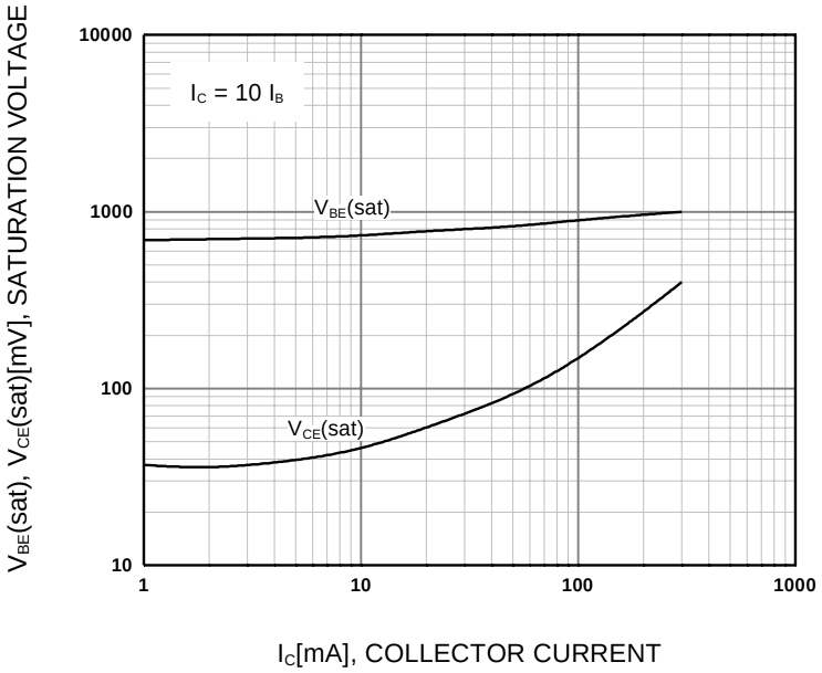
V_CE_sat is under 40 mV when collector current is under 6 mA, so I put 40 mV (and 100 mV video offset) into my spreadsheet and got these resistor values:
R2,3,4 = 390, 404, 1856.
390 is an E24 value.
404 is nearly 390 + 15 = 405
1856 = 1800 + 56 exactly
Another issues is that the 5V rail can vary by 5 or 10 percent, so ideally I'd like a precise regulated voltage. Most regulators are 5% accuracy too. What is needed is a voltage reference, which are more like 1% or better.
This 4.096V looks suitable:
2026-02-01
I was going to experiment by building stuff on a breadboard, then wondered if there was some web based circuit emulators. I found this javascript page: https://www.falstad.com/circuit/circuitjs.html
and entered my experiment. One can save and load circuits, so I saved mine (see the project files). I think it resets and forgets after a while. The circuit looks like this:
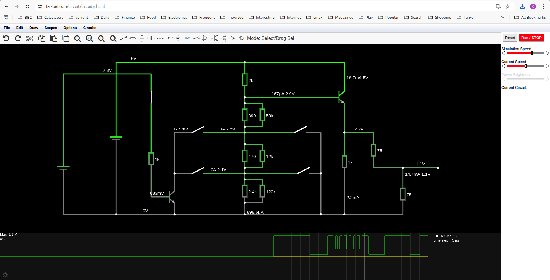
You can use either open-collector transistors or switches to test the circuit. Switches pull to exactly 0V, while transistors have about 20 to 30 mV drop. I found resistors that give the voltages I wanted (0.1, 0.4, 1.1 volts) with the default transistor models. Using the transistor input raised the sync voltage by 10 mV, and the black voltage by 9 mV. I think that will be trivial, and that the transistor parameters will vary with individual devices and temperature. Human eyes will not see much difference.
I may also try other people's circuits to see how well they were designed.
Discussions
Become a Hackaday.io Member
Create an account to leave a comment. Already have an account? Log In.