 CentyLab
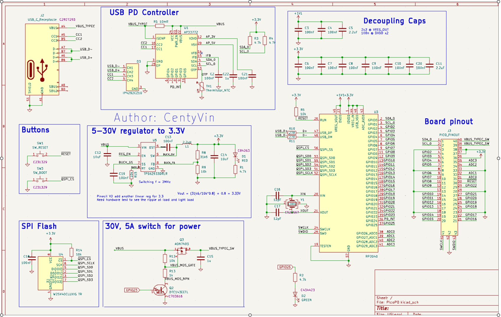
Once the first batch of the first design arrived. I was quite excited to plug it in and hope the red LED will turn on indicating that there is 5V power going into the buck converter. But nothing lights up. I also wasn't able to flash the board and run blink. A bit of debug shows that I have made some rookie mistakes:
- No 5.1k Ohm termination on CC1 and CC2 to GND
- Order DualSPI flash instead of QuadSPI flash
- SPI flash decoupling capacitor is placed too far away from the IC
- Crystal Oscillator has 80Ohm ESR instead of 50Ohm ESR recommended by Rasberry Foundation
- No series resistor to limit crystal drive
- USB trace is not set to 90Ohm differential impedance
Another Hackaday member also raised the question of how can you debug the board while providing PD power. With the current design, there are only two methods:
- Use a USB-C Splitter to have CC1 and CC2 routed between PicoPD and power brick, and have D+/D- routed between PC and PicoPD
- Use PicoProbe to program via SWD, and just plug the power brick directly into PicoPD
The AP33772 IC also can perform a "hard reset" which will cut off the power to the PicoPD temporarily. If "hard reset" is in the code, the device can stuck at a boot loop. To prevent this, a separate power supply is needed if the sole purpose is debugging.
---> 2nd design iteration is coming
Discussions
Become a Hackaday.io Member
Create an account to leave a comment. Already have an account? Log In.