 Michael Wessel
The good news is - it works!
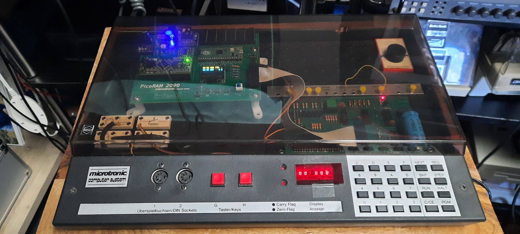

The bad news is: I'll need one more round of PCB revisions; problems are:
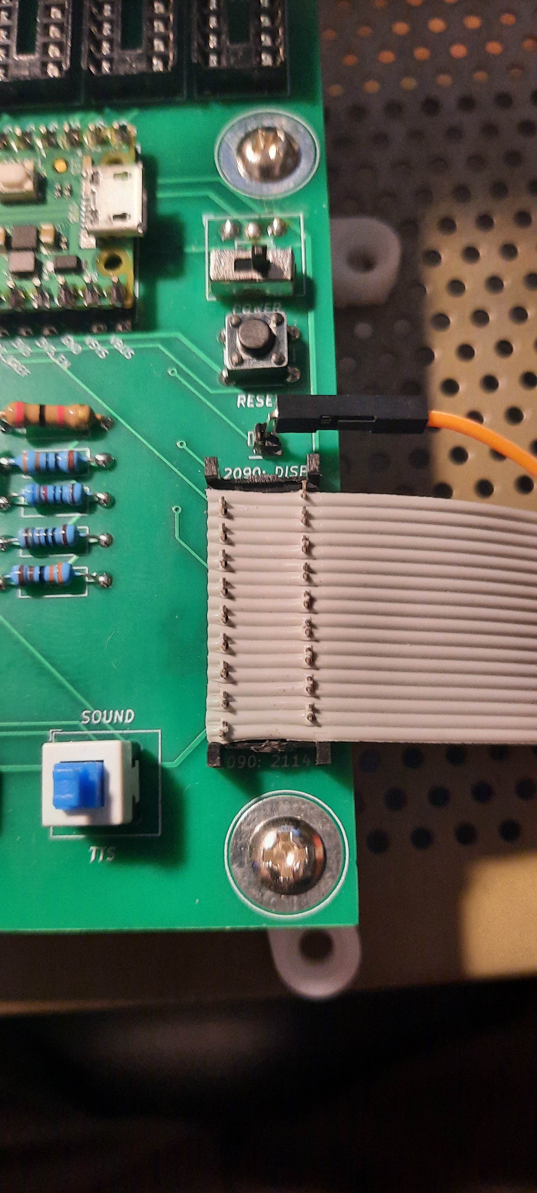
- the power switch is blocking the Pico's USB port - I hence had to put in a temporary micro slide switch which is very flimsy and a bit of a hack.
- I also learned that the double throw 6pin DPDT power blue & white switches come in 7x7 and 8x8 mm; the 7x7 that I currently have don't fit the KiCAD footprints without pin bending. So I ordered the 8x8 ones.
- the silkscreen text for buttons and button legend is too small.
- the SRAM 2114 data lines are in reverse bit order - I had to change the firmware for now by including a reverse_bits on the data lines, but have fixed this already in the PCB.
- the voltage divider for the Microtronic's DISP line is 1k-1k instead of 1k-2k... I had to cut a trace and use one of the spare 2k resistors in one of the isolated resistor network DIPs with a bodge wire.
- I made a stupid mistake when I crimped the 2114 connector cable - it took me 2 hours before I finally identified the badly crimped cable shorting every adjacent pair of wires, questioning my design, as the main culprit why it wouldn't work at all at first. I had to de-solder the crimp connector from the board and messed up a trace, requiring one more bodge wire.
Well, the 2nd revision of the PCB is already in production, and this should be the final one!
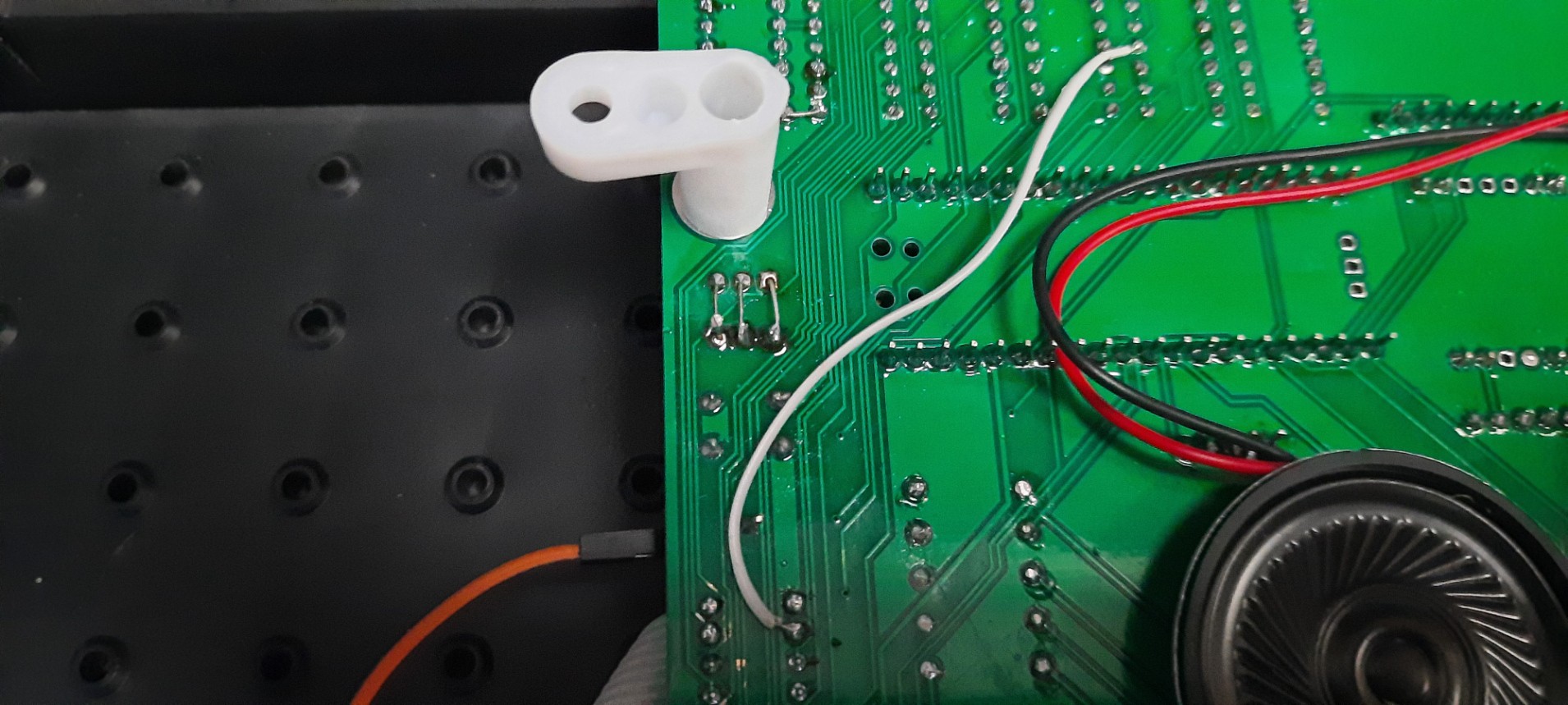
Here are a few pics of the mess ups:
Discussions
Become a Hackaday.io Member
Create an account to leave a comment. Already have an account? Log In.