As mentioned before, I decided to put the programming interface into one of the unused (at least, for our badges) pins of the SAO connector. The idea was it would be easier and faster to just plug the SAO into its intended port after assembly, rather than hooking up to testpads or something.
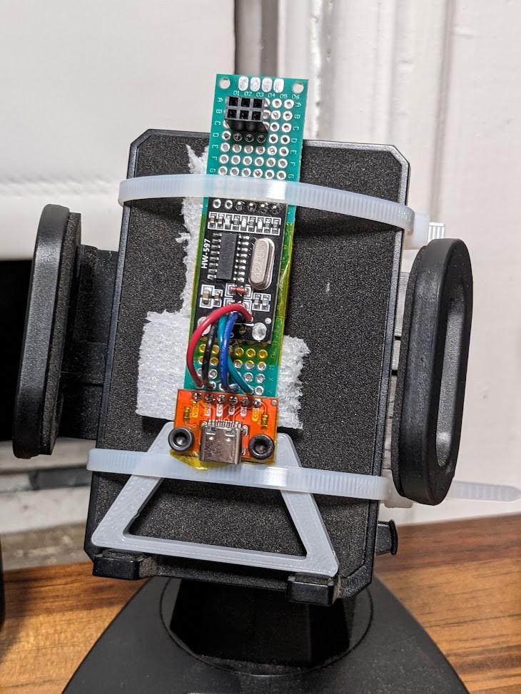
Early tests were done with a suitably modified serial adapter, but looking for something a bit more robust, I eventually came up with this programmer/stand to use while working on the firmware, since it holds the SAO at a convenient angle next to my keyboard.

This worked, but was a bit fiddly as the connections were all done with jumper wire on the back. So long as it's sitting still it will probably be fine, but while assembling these things, I wanted something I could grab without worrying about ripping out a wire.
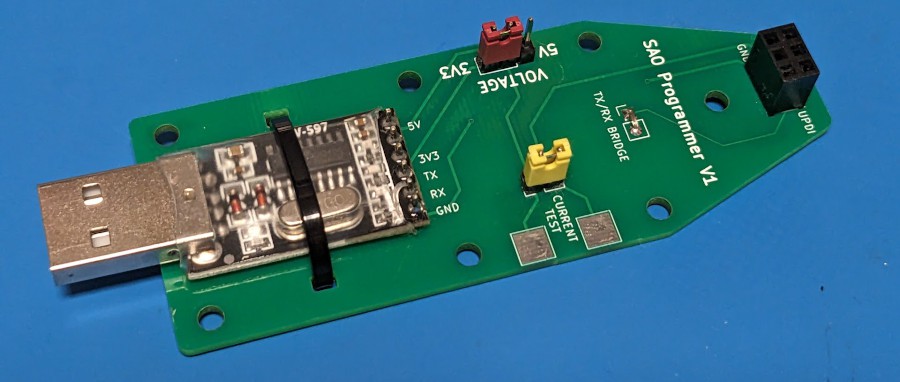
So here's the slightly more official version:

I figured if I was going to get boards made for it I might as well do it up right, so I added jumper to select between 5 and 3.3 V -- an SAO should never see 5 V, but in theory, I could program them at the higher voltage which apparently is faster. I also added some large test pads where I could clamp on leads to my meter and test the current being used by the SAO. Probably not necessary, but why not?
I used this new programmer a few times tonight, and it seems to work fine. But I do want to add a 3D printed plate on the back (which is why the screw holes are there), and potentially adapt the male USB A to something easier to use while handheld.
 Tom Nardi
Discussions
Become a Hackaday.io Member
Create an account to leave a comment. Already have an account? Log In.