 WJCarpenter
Wiring up a physically connected button with the Navien A2 is a simple job. It's a normally open switch between two contacts, and the installation manual explains it all quite clearly. An inexpensive doorbell button would do the trick. There are a couple of reasons that I don't want to use that technique.
- I don't want to run the necessary wires to the upstairs bathrooms.
- I want to integrate with Home Assistant.
- I want some kind of feedback that the button has been pressed and the pump is on. I want that not only for the location where the button was pushed, but also the other locations with buttons.
Since I have all kinds of experience with ESP8266, ESP32, ESPHome, and Home Assistant, those are the hammers with which I can pound in this nail. Other than being a normally-open switch, I'm not too sure of the electrical characteristics of the hard-wired buttons. Instead of having fun figuring that out, I decided to use a digitally controlled relay. The idea is that I can send some kind of command to the circuit, and that would cause the relay to be briefly closed to simulate a button push.
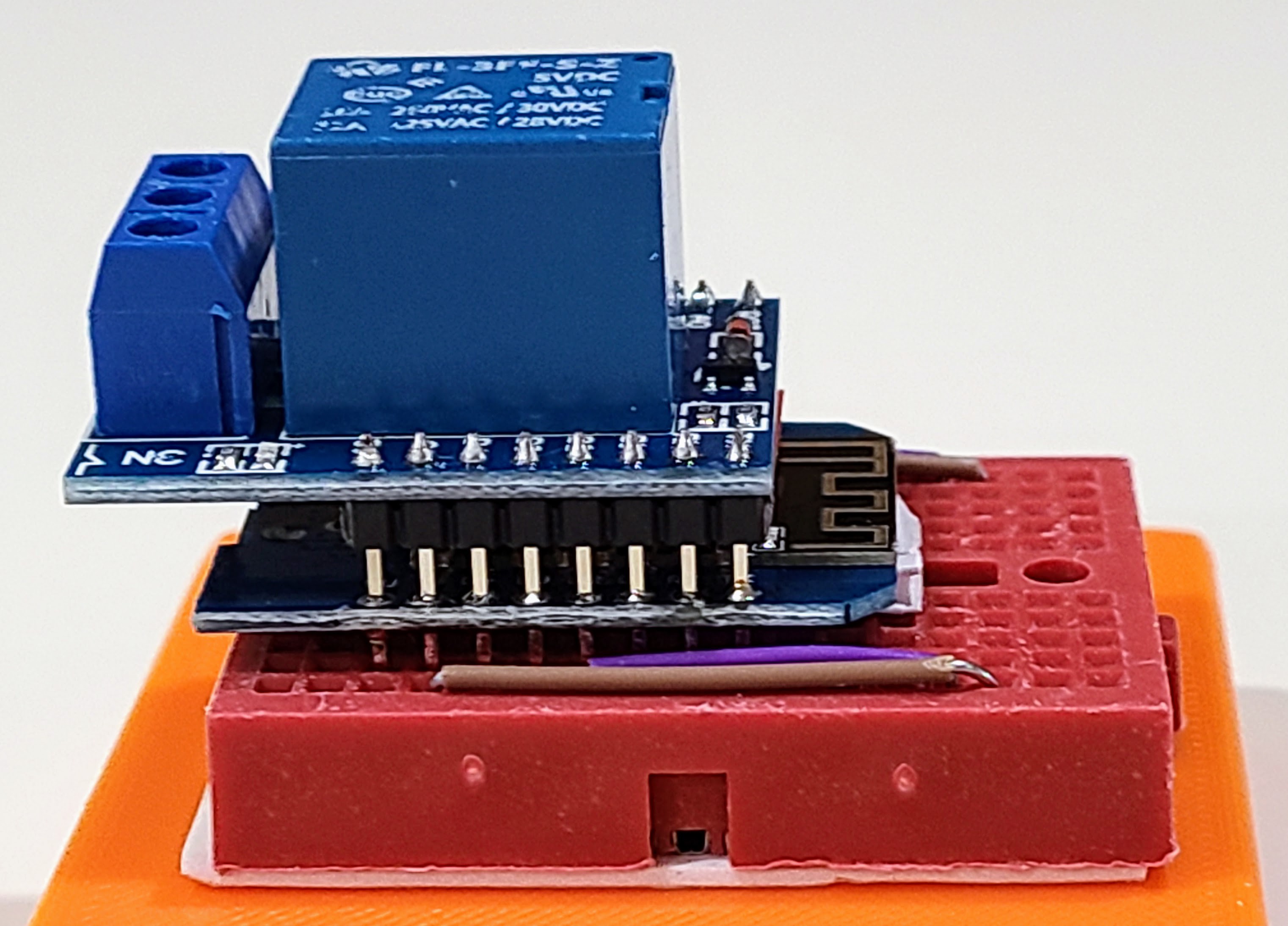
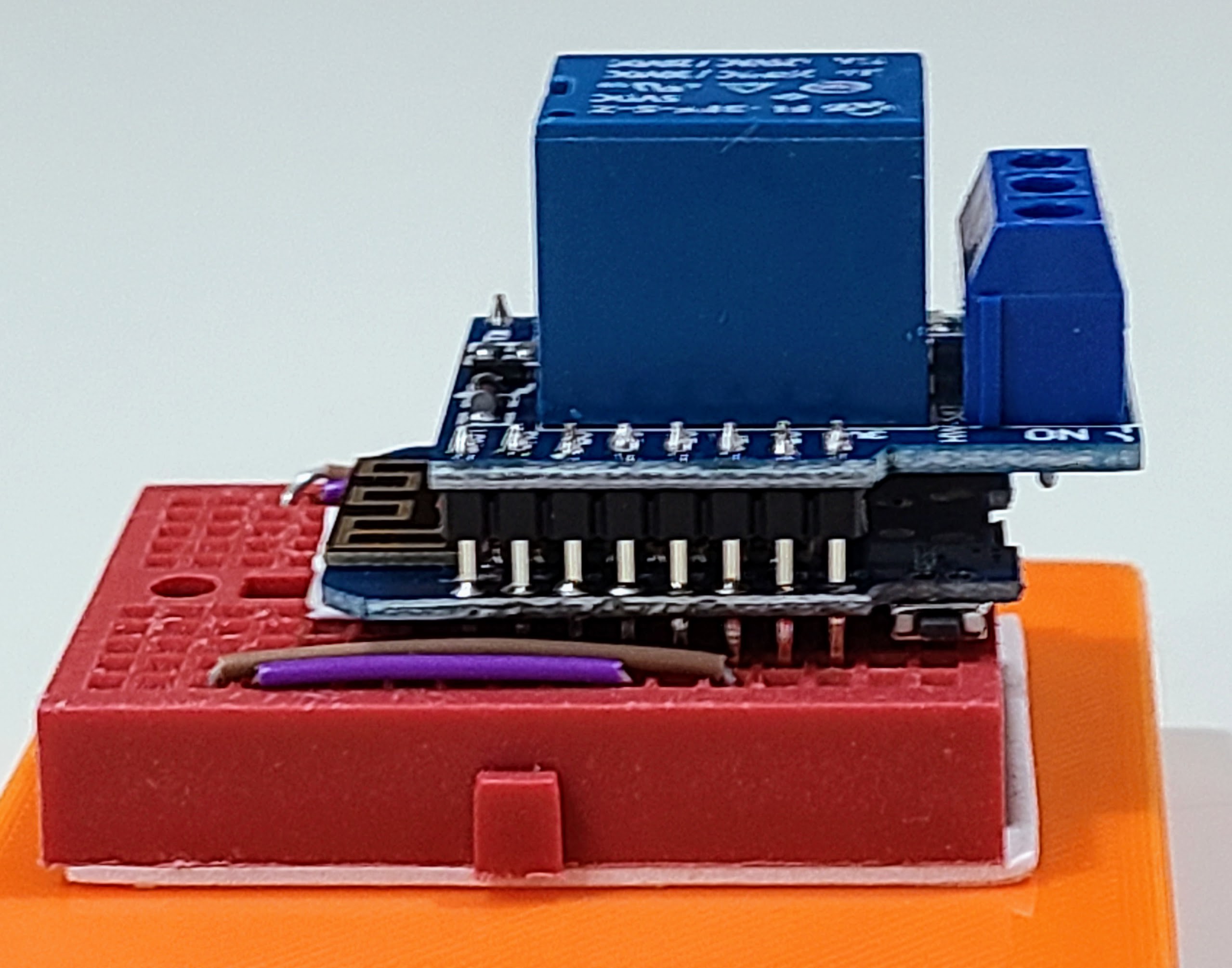
I didn't want to bother with a PCB for such a simple circuit. I have a few Wemos D1 Mini boards (ESP8266) already, and it's easy to find relay shields that are made to mate with the D1 Mini. Putting things together with normal stacking pin headers works, but it makes things fairly tall. Obviously, that's only an aesthetic consideration. From a previous project, I had some extra long male pin headers. I soldered those to the relay board and then pushed them through and soldered them again to the D1 Mini. I left a small gap, but I also put a little piece of electrical tape on the metal can of the ESP8266 as a precaution against shorting something on the relay board. That still left enough pin length to make a good connection inserted into a mini breadboard.
Here are some pictures of the resulting stack. It's still pretty tall, but there's only so much you can do with the height of the relay on the relay board.
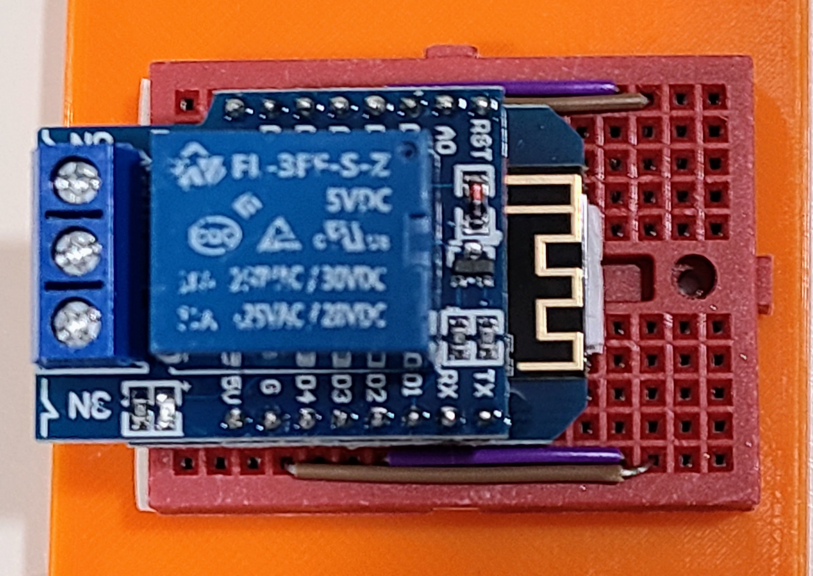
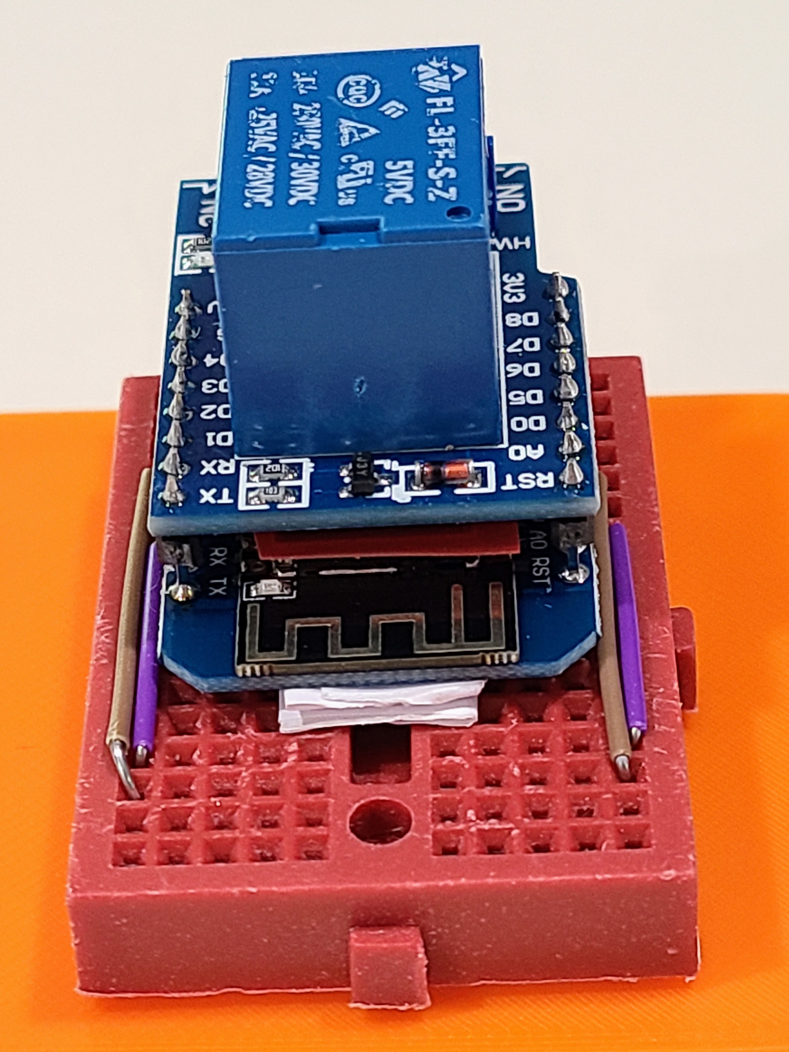
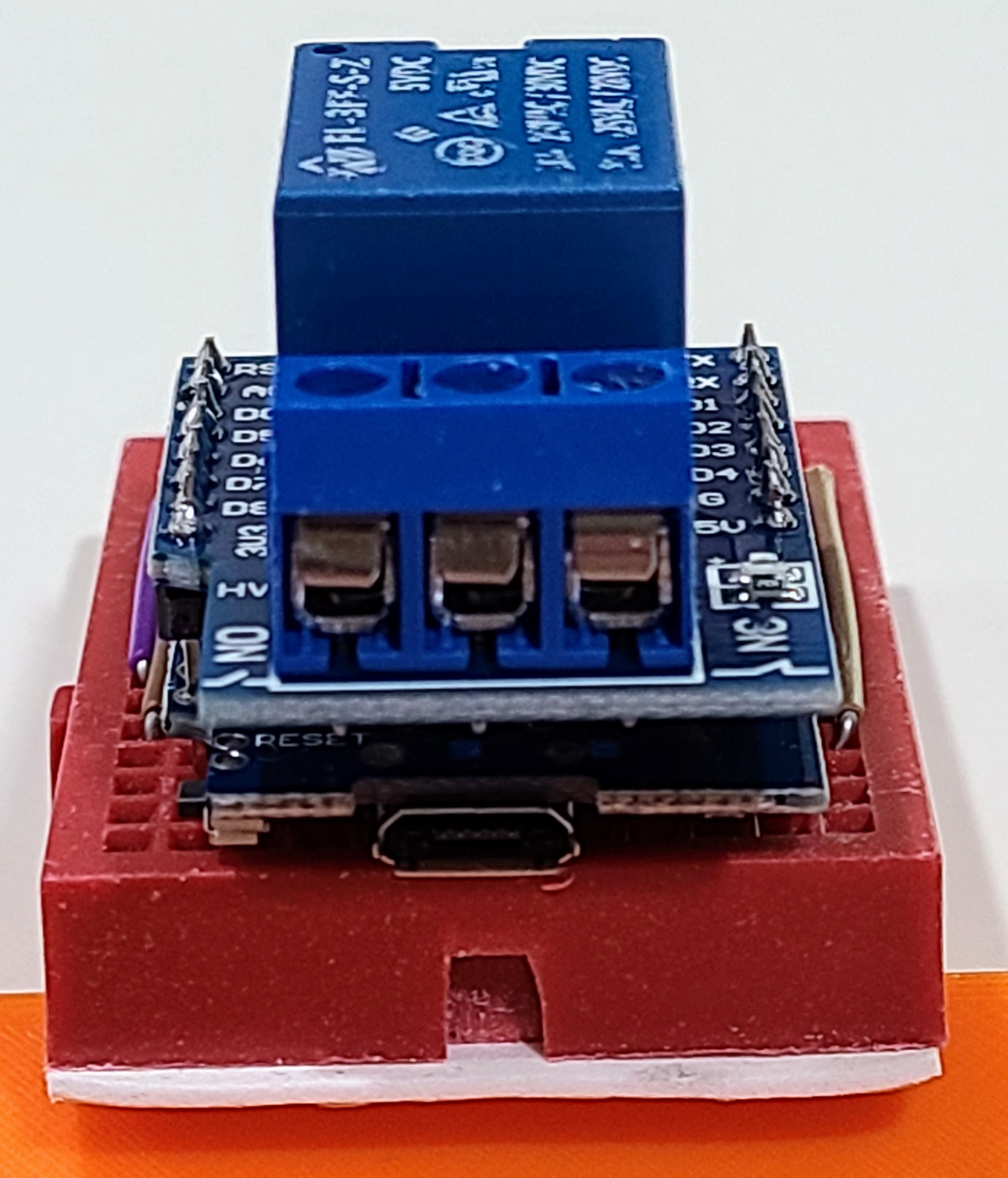
I wedged some folded paper under the antenna end of the D1 Mini to keep it from wobbling. The relay board sticks out a bit beyond the end of the D1 Mini. I imagine that's intentional. The contacts from the relay are slightly off-center compared to the micro USB port of the D1 Mini. However, if you look at the end of the relay board itself compared to the end of the D1 Mini, the offset is somewhat larger.
I originally mounted the boards all the way at one end of the mini breadboard, but I later decided to move everything back two rows for a more comfortable fit in the enclosure. The jumpers you see in the photo are for additional purposes that I'll describe in a later project log, but I used the jumpers so I would have more working room when it comes time to wire up other things.
Discussions
Become a Hackaday.io Member
Create an account to leave a comment. Already have an account? Log In.