Close
0%
0%

CLN17 V2: $12 BoM Closed-Loop Driver for NEMA17

A compact, silent, high-performance open-source closed-loop (servo) stepper motor driver with USB, CAN-FD and 48V support

Similar projects worth following
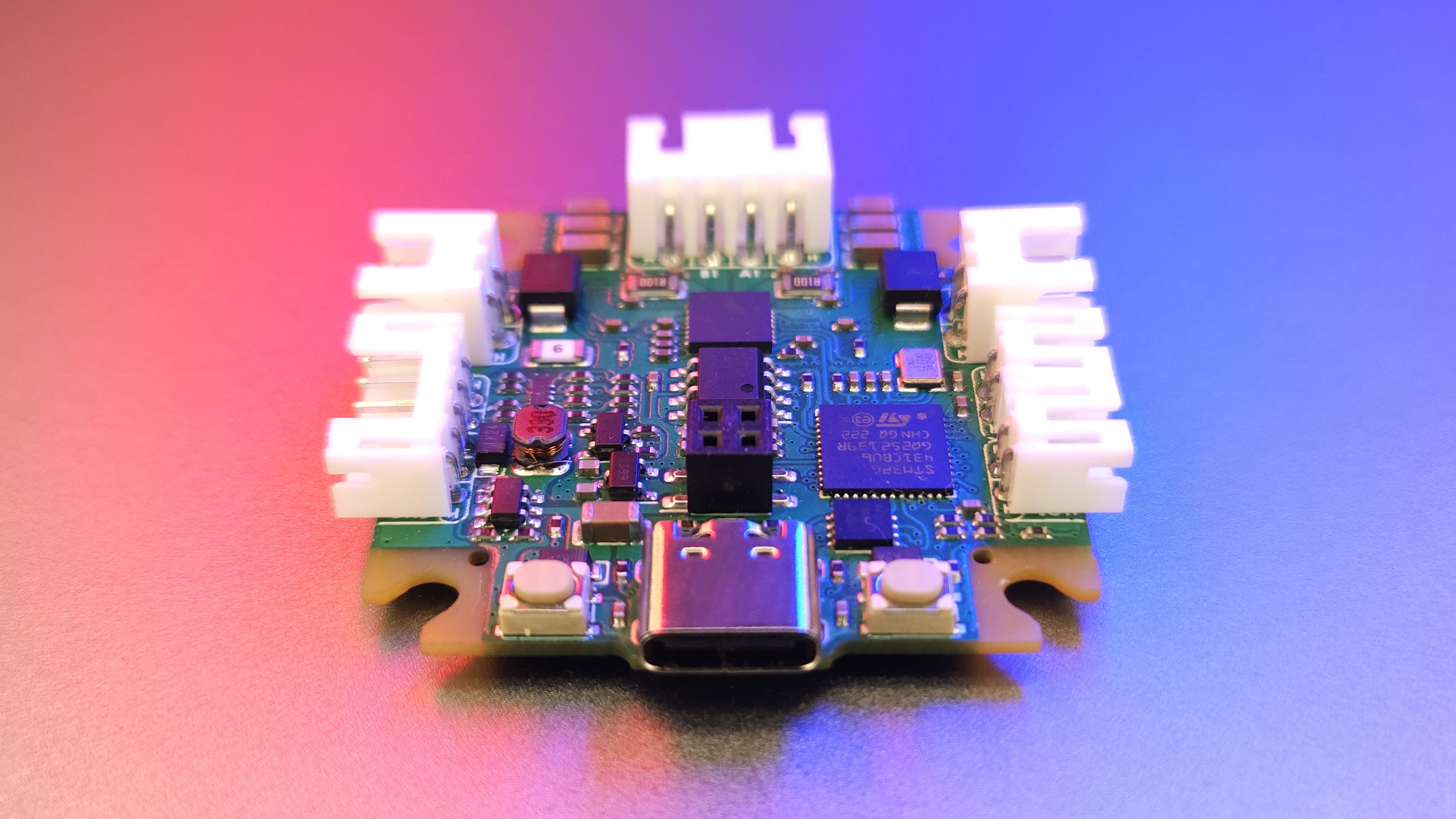
The CLN17 motor driver is an affordable, open-source, compact, high-performance closed-loop stepper motor driver designed specifically for NEMA17 form factor motors. The driver offers advanced features such as silent and smooth motion, high-precision position control, and energy-saving capabilities, making it ideal for various applications.

This project wasn't merely born as yet another driver; it was envisioned as a mighty instrument for education, development, experimentation, and the modeling of mechanical systems. Its mission? To resolutely meet every requirement and address all the needs that may arise during the journey with stepper motors, once and for all!

The project is actively evolving and improving! If you wish to be a part of it, ask questions, or simply watch its progress, join the project's Discord server - discord.gg/D4EkKaf5vV.

Driver development will lead to content updates on the project repo - https://github.com/creapunk/CLN17. Stay tuned!

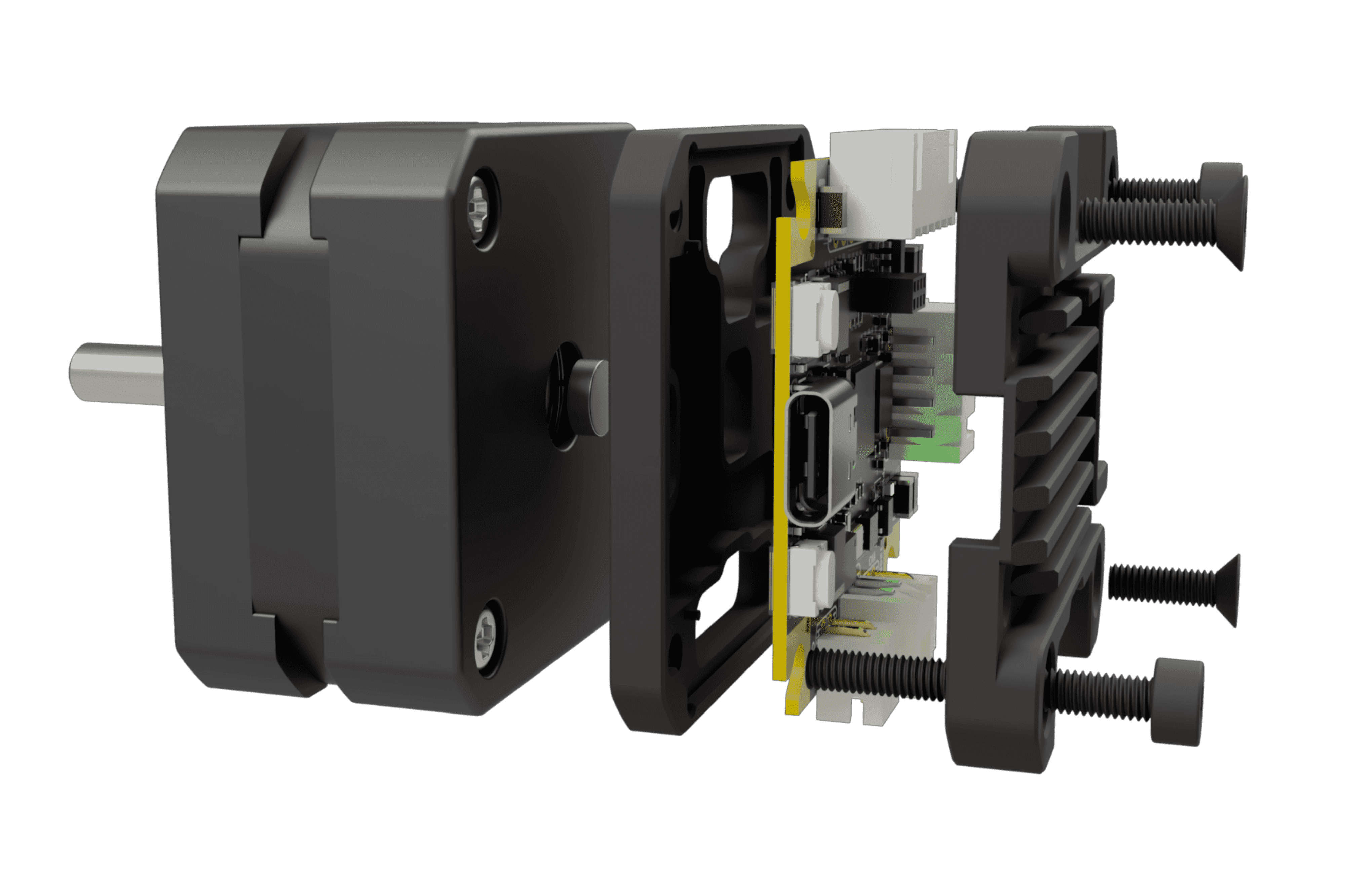
Assemly preview

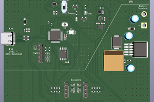
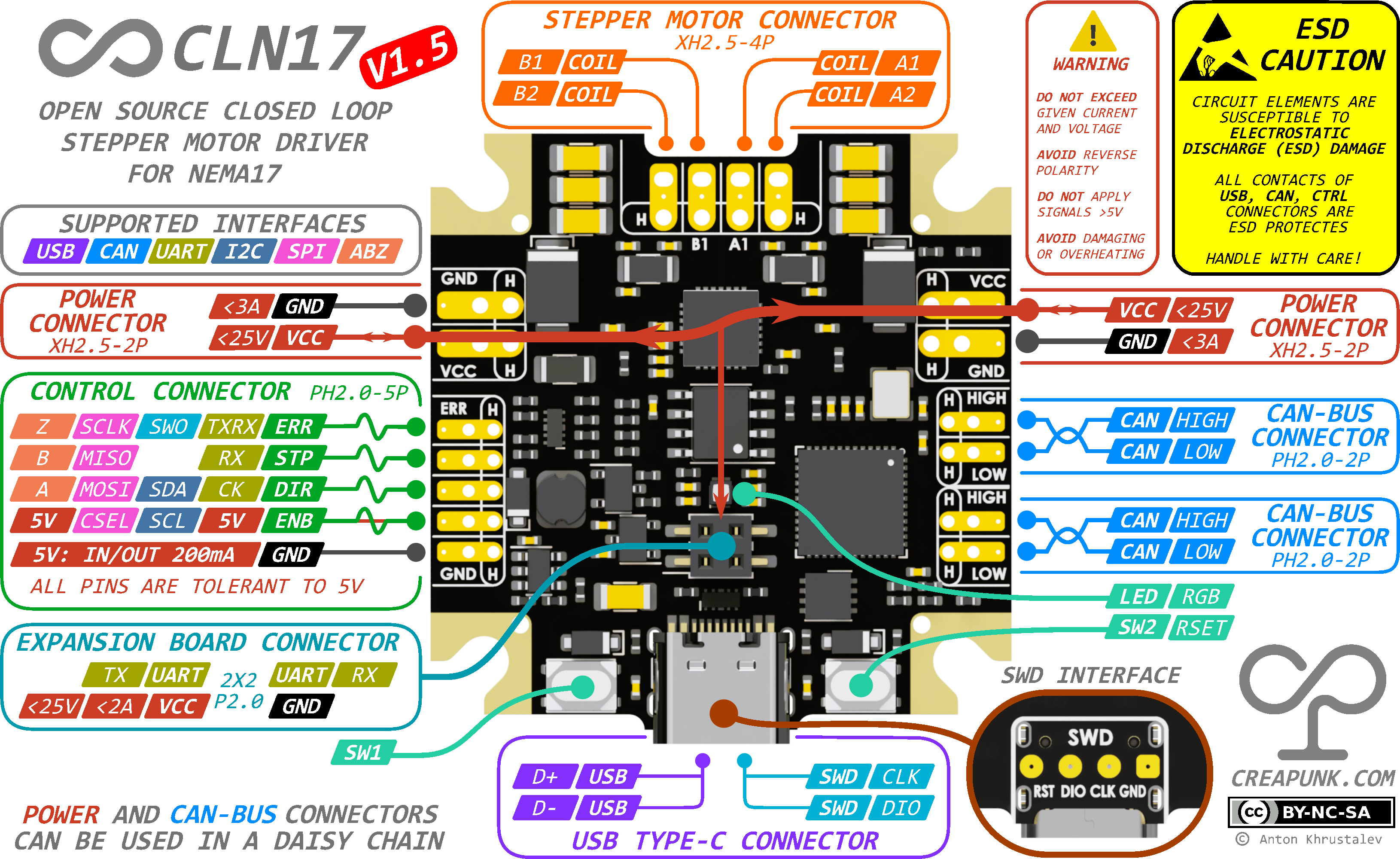
Board Diagram
Key Features | All Features

  • 🕹️ Closed-Loop Control: Enables precise motion in challenging conditions.
  • 💪 Adaptive Torque Control: Optimizes energy efficiency, reduces stress, and extends motor lifespan.
  • 🧩 Reliable Operation and Enhanced Safety: Ensures reliable operation and protects users from potential harm.
  • 🛡️ Modular Concept: Provides flexibility and cost-effectiveness through various configurations and expansion boards.

Key Specs | All Specs

  • 🔌 Wide Input Voltage Range: 8-48VDC with reverse polarity and surge protection
  • ⚡️ Powerful Motor Control: 1.75A RMS current per phase with up to 2A peak
  • 🚀 High-Performance MCU: STM32G431CB Arm Cortex-M4 running at 170MHz with Classic EN/DIR/STEP interface, CAN-Bus, I2C, UART and USB Type-C
  • 🔒 Compact and Durable Design: 38x38mm PCB, with optional aluminum housing for heat dissipation and mechanical protection and minimal height of 7.5mm (10mm with connectors)

Applications | In-depth

  • 🎓 Learning Platforms
  • 🛠️ CNC Machines & 3D printers
  • 🤖 Robotics & Automation Systems
  • 🤝 Collaborative Robots
  • 🔭 Camera & Telescope Stabilization Systems
  • 🔬 Laboratory Equipment
  • 🏭 Industrial Motion Control Systems
  • 📳 Haptics & Force Feedback Systems

What is the project's status?

There are numerous updates planned for the documentation, including the publication of articles on related topics. Alsowill be provided insights into development process, announce new versions, introduce new features, and much more. Visit GitHub page for details!

Design Overview

To fully grasp the design intricacies of the CLN17 project, it is recommended to familiarize yourself with its foundational principles, as they provide the conceptual basis for CLN17. Also see the CC BY-NC-SA 4.0 license.

  • 1 × CLN17 PCBA For control the motor
  • 1 × NEMA17 Stepper Motor The motor as it is
  • 1 × Diametrically magnetized magnet D5xH2mm To determine the shaft orientation with a magnetic encoder
  • 1 × Aluminum enclosure For positioning, securing, protecting and cooling the board
  • 2 × DIN912 M3 For securing to the motor

View all 7 components

  • CLN17 V2

    Anton Khrustalev03/26/2024 at 10:02 0 comments

    After six months of dedication, I'm thrilled to present what I've been working on recently! Check out the video for all the details! 🎬

    Stay updated with the latest news and updates in our Discord community and on GitHub!

  • New Enhanced Hardware!

    Anton Khrustalev01/28/2024 at 10:58 0 comments

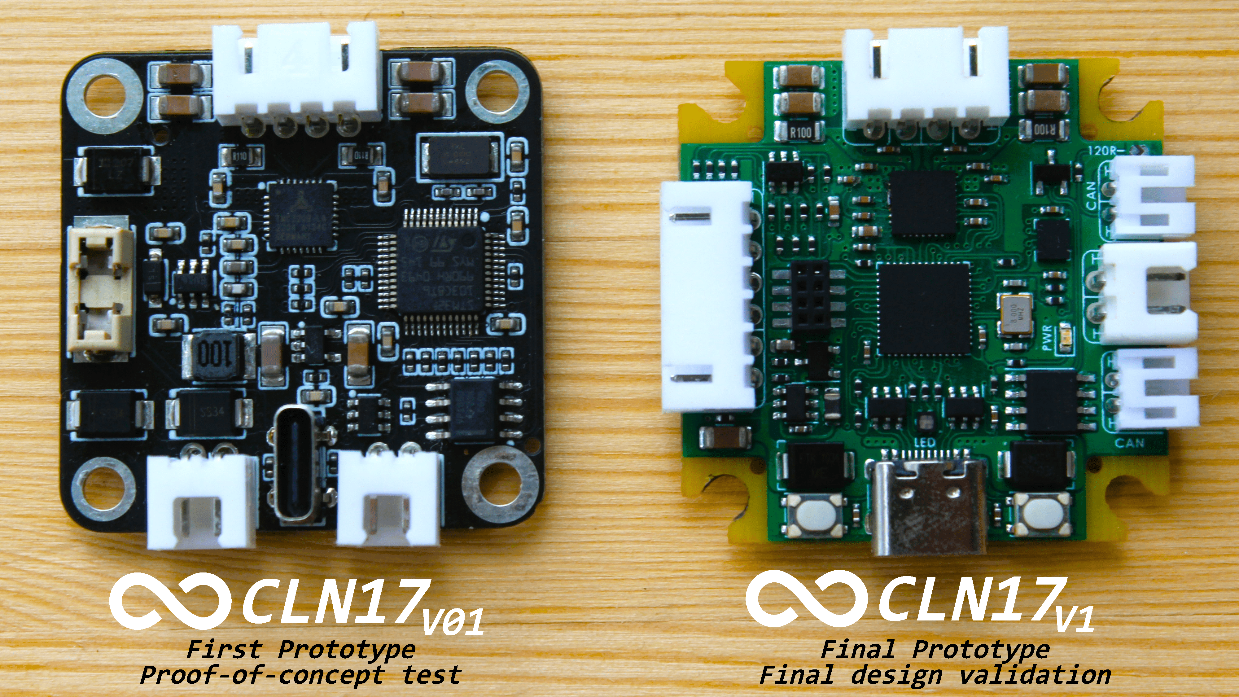
    After some time and great interest in the project, I've decided to release a new version that boasts numerous improvements over V1.0.

    Presenting a refined and enhanced CLN17, a fixed and improved version of CLN17!

    This iteration is designed to encounter fewer issues and introduce a plethora of new functions. A standout feature is the daisy chain capability for the power supply, alongside expanded functionalities for the CNTRL connector. Now, a single connector with 4 signal pins supports:

    • STEP-DIR-EN-ERR interface
    • USART (Synchronous/Asynchronous/SingleWire)
    • I2C
    • SPI/SSI (ideal for an external magnetic encoder)
    • ABZ input for an external incremental encoder, complemented by a supportive pin supplying 4.5V at 150mA.

    There are a few limitations regarding interface overlap, but with the addition of CAN-FD and USB, I believe I've covered all bases! The hardware is fully operational and devoid of any identified or critical issues. It can be considered a complete and final version.

    Moreover, this version features a single-sided design and includes numerous optimizations!
    The source files are already available on GitHub!

    Another version of the driver, designed for 48V 1.75A (with an absolute limit of 55V 2A), is currently in the testing phase. Also a version for high-current, large motors like Nema23/Nema34/Nema42 is in the design stage!

    If you appreciate the project and wish to support its development, you can do so through:

    • Ko-fi (preferred for membership subscriptions and one-time donations): Here, you can sign up for monthly support or make a one-time donation as well!
    • Patreon: Similar to Ko-fi, but with higher fees.

    Stay connected and follow the updates, join project Discord!

    Special thanks to JLCPCB for sponsoring the board manufacturing of this design!

  • Note about USB Type-C and board programming

    Anton Khrustalev09/26/2023 at 13:56 0 comments

    In many small-scale embedded projects, the Type-C connector has historically seen limited use. However, there's a noticeable shift towards its adoption in recent times.

    For the most part, Type-C acts as an up-to-date substitute for the now-obsolete Mini-USB or Micro-USB connectors. Their primary roles have been to provide 5V power and to function as a USB2.0 interface. Let's sidestep the frequent oversight by some developers who forget to incorporate the 5.1k resistors.

    Yet, the utility of Type-C extends far beyond merely replacing aged connectors!

    Note: This discussion excludes Type-C configurations that necessitate USB3.0 or the 24-pin connector due to their intricate design.

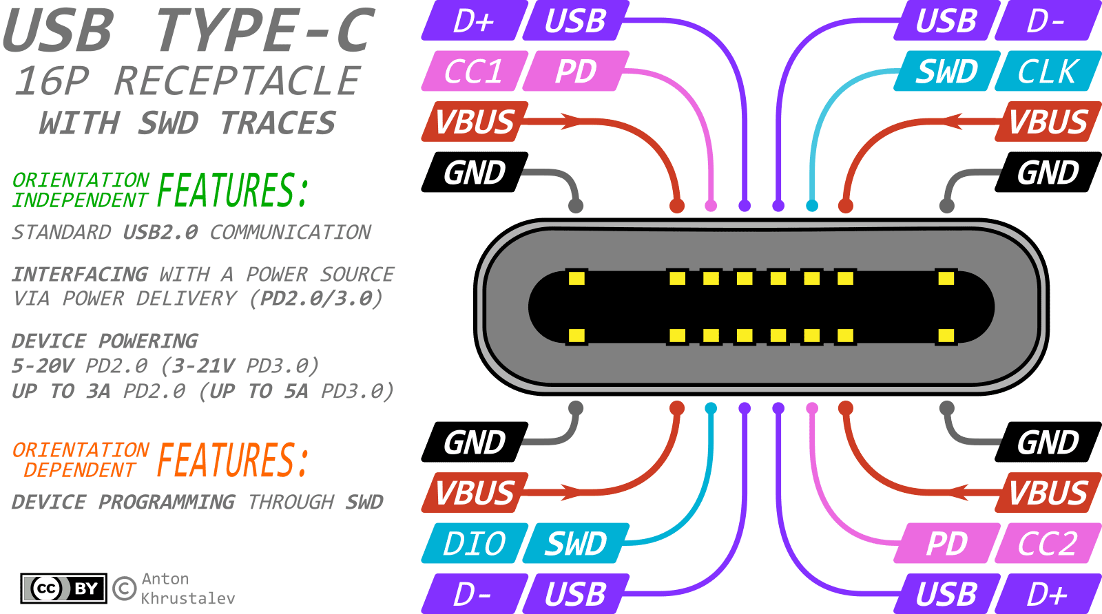
    A popular adaptation of Type-C is the 16-Pin variant:

    • 8 pins are used for power (4 for GND and 4 for VCC to withstand currents up to 3A or 5A - check datasheet for connector)
    • 4 pins are used for orientation-independent USB 2.0 (2 for D+ and 2 for D-)
    • 2 pins, CC1 and CC2 (Configuration Channel), are used for PowerDelivery communication
    • 2 pins, SBU1 and SBU2 (SideBand Use) - are nt used except for 'alternate mode' or 'Audio Accessory Mode'.

    Employing PowerDelivery can yield voltages and currents ranging from:

    • 5-20V at 5A (max 100W) for PD2.0
    • 3.3-21V at 5A (max 100W) with 20mV steps in PPS mode for PD3.0
    • 3.3-48V at 5A (max 240W) with 100mV steps in PPS+EPR mode for PD3.1.

    However, two pins in the connector – SBU1 and SBU2 – often remain untouched. They're designated for 'alternate modes' that rely on USB3.0 signaling lines. Since many projects bypass USB3.0, these pins stay dormant. But consider the potential: what if we repurpose these pins for debugging or programming? Imagine using them for the SWD or UART interfaces, both of which require just two lines! For example

    In terms of compatibility, the Type-C standard dictates that the impedance of inactive SBU lines should exceed 950kOhm. With CMOS-based communications (like UART and SWD), this specification is almost always met. Additionally, if a Type-C cable lacks USB3.0 support, it likely won't carry SBU signal lines, eliminating potential concerns. And given the resilience of UART and SWD protocols, coupled with their data integrity checks, inadvertent mishaps are unlikely.

    Advantages:

    • Single connector on the board, ensuring reliable contact.
    • Eliminates the need for bulky programming pads, especially in micro-projects.
    • Debugging flexibility with extended cables.
    • Firmware updates without having to disassemble the device.

    Drawbacks:

    • Mandatory attention to Type-C orientation since signaling is orientation-specific.
    • Programming requires a slightly pricier Full Featured Type-C Cable.
    This is a raw note, will be corrected late

    Linked project: #SWD over USB Type-C: New way of programming boards 

  • Theoretical and real positioning accuracy

    Anton Khrustalev09/26/2023 at 13:50 3 comments

    The motor driver allows for position control down to a microstep of 1/256 (<0.01°), while the encoder has a maximum resolution of 15 bits (0.01°). Although theoretical accuracy should be close to 0.01°, it is not achievable in practice due to four factors:

    1. Motor imperfections: The construction of stepper motors commonly causes step size deviations of 2-5% in the degree measure.
    2. Step interpolation non-linearity: Increased difficulty in positioning is caused by a significant torque decrease with interpolation increase, in combination with the mechanical nonlinearities of the mechanical construction.
    3. Encoder imperfections: The effective resolution may be less than 15 bits due to nonlinearity of encoder measurements, variations in operating temperature, or interference with external magnetic fields.
    4. Magnet imperfections: The magnetic field profile created by the magnet may not rotate correspondingly to the encoder's center because of potential misalignment of the magnet and the shaft or manufacturing defects of the magnet itself.

    To achieve optimal motor performance at the maximum effective resolution, it is not recommended to exceed an interpolation of 1/64 of a full step, with an optimal limit of 1/32. Exceeding these limits can lead to a significant loss in torque without any improvement in positioning accuracy, due to mechanical nonlinearities. To maintain the encoder's linearity and minimize noise, the minimum usable resolution should not exceed half of the full resolution, resulting in a maximum resolution of 14 bits.

    As a result, the maximum approximately linear actual positioning resolution is 12,800 positions per revolution, and the actual position control resolution is 16,384 positions per revolution (0.02° step). Assuming this, the closed-loop system operates as expected and is capable of error-free shaft position correction.

    Resolution at high speeds and loads

    For high-speed or high-torque applications, it is not recommended to exceed a positioning resolution of 1/32 of a full step or 6,400 steps per revolution.

  • Power Connectors Interconnection

    Anton Khrustalev09/26/2023 at 13:48 0 comments

    The USB Type-C and power connectors (both XH2.5) are connected in parallel. Each XH2.5 connector is equipped only with a protective resettable fuse rated at 2A, while the USB Type-C has only a protective diode. Therefore,

    • The USB Type-C can provide power to the system up to 20V 3ARMS (5A peak).
    • Each one at a time XH-2.5 can provide power to the system up to 25V 2A.
    • Current transit from USB Type-C to any of the XH2.5 connectors is also possible with a current of up to 2A.
    • Current transit from one XH-2.5 to another is possible with a current of up to 2A.
    Simultaneous use of several power sources
    To avoid damaging the power supply, do not connect two different voltage sources to the XH2.5 connectors or apply power to the USB Type-C and XH2.5 connectors simultaneously, if the USB voltage is higher than the XH2.5 connector's voltage (VXH < VUSB).
    The maximum current rating of a fuse
    The maximum current rating of a self-resetting fuse decreases with rising ambient temperature. For example, at 25°C, the fuse can carry up to 2A, but at 85°C, the maximum current drops to 0.8A.

    This power architecture allows flexible and efficient power distribution across a device network. For example, with 7.5W motors (like Nema17 34mm body length), you can power the driver through a USB Type-C 20V 3A connection, and the POWER connector can supply five similar motor assemblies.

    Network driver connection
    When connecting additional drivers, it is crucial to ensure that the total current passing through the connector at any given moment does not exceed 2A. This limitation allows for a greater number of drivers to be connected, as long as they are not all operated simultaneously.
    For powering the network of drivers, it is highly recommended to use a star topology instead of a linear one. Excessive transitions through the drivers should be avoided as they can result in unnecessary heat losses.

  • Driver Powering Options

    Anton Khrustalev09/26/2023 at 13:44 0 comments

    The CLN17 operates within a 5-25V range, which is protected by a 26V surge protection TVS diode. While the TMC2209 driver recommends a 6-29V power range, operations with less than 500mA current can work at 5V.

    There are 3 options available for powering the driver:

    1. USB Type-C Connector: Default 5V 3A, can support up to 20V 3A (5A peak) with Power Delivery.
    2. XH2.5 2Pin POWER Connector: Accepts a 5-25V power source, with a maximum 3A (2.5ARMS recommended).
    3. XH2.5 6Pin CONTROL connector with power lines: Accepts a 5-25V power source, with a maximum 3A (2.5ARMS recommended).

    Operating near the lower limit of the supply voltage

    The 5V supply voltage is sufficient for low-power operations with total coil currents lower than 500mA.
    At least a 6V supply voltage is required for safe operation at the maximum permissible currents.

  • Alternative Closed-Loop Drivers

    Anton Khrustalev09/26/2023 at 12:39 0 comments

    CLN17 is not the only closed-loop motor driver. There are several alternatives available, which are also closed-loop drivers and designed with a similar architecture. These drivers comprise a microcontroller, an encoder, and a driver, all integrated onto a single printed circuit board placed at the rear side of the NEMA17 motor.

    Quick overview of the alternatives

    A comparative table of thiese drivers can be found here

    Is there anything else?

    There are several other similar products available, but they haven't been described due to the project's confidentiality or lack of information.

  • Design philosophy

    Anton Khrustalev09/26/2023 at 12:34 0 comments

    In any project, the philosophy  have a significant impact on its vision and purpose, extending beyond basic functionality. Incorporating design principles into the project can result in a solution that not only fulfills technical requirements but also resonates with users on an aesthetic level.

    • 📖 Open Source and Comprehensive Documentation: Adopting an open-source philosophy invites wide-ranging engagement, making the project versatile and adaptable. Community involvement fosters innovation and knowledge exchange, creating a supportive ecosystem. Clear documentation promotes learning, collaboration, and seamless integration with other projects.
    • 💎 Aesthetic Appeal and Usability: A technical product's aesthetic appeal should be a byproduct of its superior functionality, technological advancement, and usability.
    • 💰 Cost-Effectiveness and Accessibility: Balancing cost and functionality while prioritizing accessibility ensures the project's seamless integration across various sectors.
    • 🚀 Future-Proofing: Incorporating foresight for future improvements while maintaining the core design's integrity streamlines the development of new products. Proactively addressing and accommodating future requirements ensures the project's enduring viability and relevance.

  • Design concepts

    Anton Khrustalev09/26/2023 at 12:33 0 comments

    • 💪High Performance: The system should be capable of processing feedback data in real-time and react immediately by controlling the motor based on predefined algorithms. This simplifies the control process and reduces the load on the control device.
    • 💻 Compatibility and Versatility: A wide range of supported interfaces should enable interaction with existing protocols as well as the implementation of new ones. This expands compatibility and facilitates integration of the device into existing systems.
    • 🛡️ Precision and Fault Tolerance: The implementation of feedback control with position and current sensors should ensure precise positioning and mechanical load monitoring. This enables the detection and prevention of abnormal system operation when necessary.
    • 🔧 Adaptability: Evaluating motor operating parameters and system displacement data enables the selection of an optimal motor control profile for the specified task.
    • ⚡️ Reliability and Power Efficiency: Providing protection against electrostatic discharge (ESD), short circuits, and reverse polarity, as well as preventing overheating through reduced thermal losses, improved heat dissipation, and enhanced energy efficiency.
    • 🧩 Customizability and Modularity: The device should accommodate functionality expansion or reduction without necessitating design changes.
    • 🏭 Optimized for Design for Manufacturing (DFM): Complying with manufacturing technology requirements enhances manufacturability while reducing production costs and complexities.
    • ⏳ Longevity Considerations: When choosing project component composition, future availability and support forecasts should be considered.

  • The Journey: Functional Prototype

    Anton Khrustalev09/12/2023 at 13:14 0 comments

    After an extensive development process which involved numerous design iterations and reconsideration of implementation methods, the updated project version that encompasses all concept ideas has been released!

    Compared to the previous version, the PCBA is more:

    • Compact
    • Powerful
    • Functional
    • Equipped with numerous safety features

    It has now evolved from being just another driver to becoming a powerful tool for education, development, testing, and system modeling.

    Does it work? The short answer is yes. However, diving deeper, things get a bit more complicated.

    From a hardware perspective, there are a few minor issues, which fortunately don't have an impact on the primary functionality. These known issues include:

    • Incorrect polarity of the power indicator LED;
    • Not stable behavior of the buck DCDC converter at voltages below 6V

    Apart from these, all other driver functions operate correctly.

    On the code side of things, it's a different story. A vast amount of work is still needed to release the complete driver control library that would unlock its full potential. But there's hope that it's just a matter of time.

View all 12 project logs

  • 1
    Complete Project Documentation

    All the latest project documentation can be found at creapunk.com/cln17

View all instructions

Enjoy this project?

Share

Discussions

Petar Crnjak wrote 09/17/2023 at 16:21 point

Hey, great project! Where can I find the code it is not on gihtub.

  Are you sure? yes | no

Anton Khrustalev wrote 09/17/2023 at 16:29 point

Thank you! The project is still in the works, so the release of source files and software is planned after successful tests. Follow updates on this page or in the Discord community!

  Are you sure? yes | no

Similar Projects

Does this project spark your interest?

Become a member to follow this project and never miss any updates