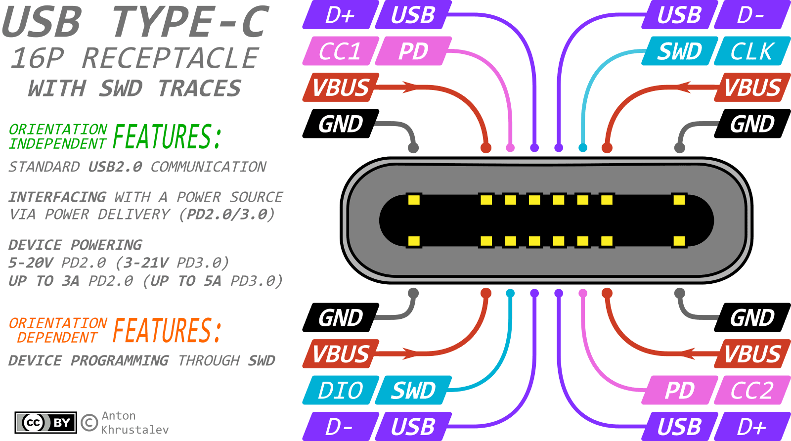
In many small-scale embedded projects, the Type-C connector has historically seen limited use. However, there's a noticeable shift towards its adoption in recent times.
For the most part, Type-C acts as an up-to-date substitute for the now-obsolete Mini-USB or Micro-USB connectors. Their primary roles have been to provide 5V power and to function as a USB2.0 interface. Let's sidestep the frequent oversight by some developers who forget to incorporate the 5.1k resistors.
Yet, the utility of Type-C extends far beyond merely replacing aged connectors!
Note: This discussion excludes Type-C configurations that necessitate USB3.0 or the 24-pin connector due to their intricate design.
A popular adaptation of Type-C is the 16-Pin variant:
- 8 pins are used for power (4 for GND and 4 for VCC to withstand currents up to 3A or 5A - check datasheet for connector)
- 4 pins are used for orientation-independent USB 2.0 (2 for D+ and 2 for D-)
- 2 pins, CC1 and CC2 (Configuration Channel), are used for PowerDelivery communication
- 2 pins, SBU1 and SBU2 (SideBand Use) - are nt used except for 'alternate mode' or 'Audio Accessory Mode'.
Employing PowerDelivery can yield voltages and currents ranging from:
- 5-20V at 5A (max 100W) for PD2.0
- 3.3-21V at 5A (max 100W) with 20mV steps in PPS mode for PD3.0
- 3.3-48V at 5A (max 240W) with 100mV steps in PPS+EPR mode for PD3.1.
However, two pins in the connector – SBU1 and SBU2 – often remain untouched. They're designated for 'alternate modes' that rely on USB3.0 signaling lines. Since many projects bypass USB3.0, these pins stay dormant. But consider the potential: what if we repurpose these pins for debugging or programming? Imagine using them for the SWD or UART interfaces, both of which require just two lines! For example

In terms of compatibility, the Type-C standard dictates that the impedance of inactive SBU lines should exceed 950kOhm. With CMOS-based communications (like UART and SWD), this specification is almost always met. Additionally, if a Type-C cable lacks USB3.0 support, it likely won't carry SBU signal lines, eliminating potential concerns. And given the resilience of UART and SWD protocols, coupled with their data integrity checks, inadvertent mishaps are unlikely.
Advantages:
- Single connector on the board, ensuring reliable contact.
- Eliminates the need for bulky programming pads, especially in micro-projects.
- Debugging flexibility with extended cables.
- Firmware updates without having to disassemble the device.
Drawbacks:
- Mandatory attention to Type-C orientation since signaling is orientation-specific.
This is a raw note, will be corrected late
 Anton Khrustalev
Discussions
Become a Hackaday.io Member
Create an account to leave a comment. Already have an account? Log In.