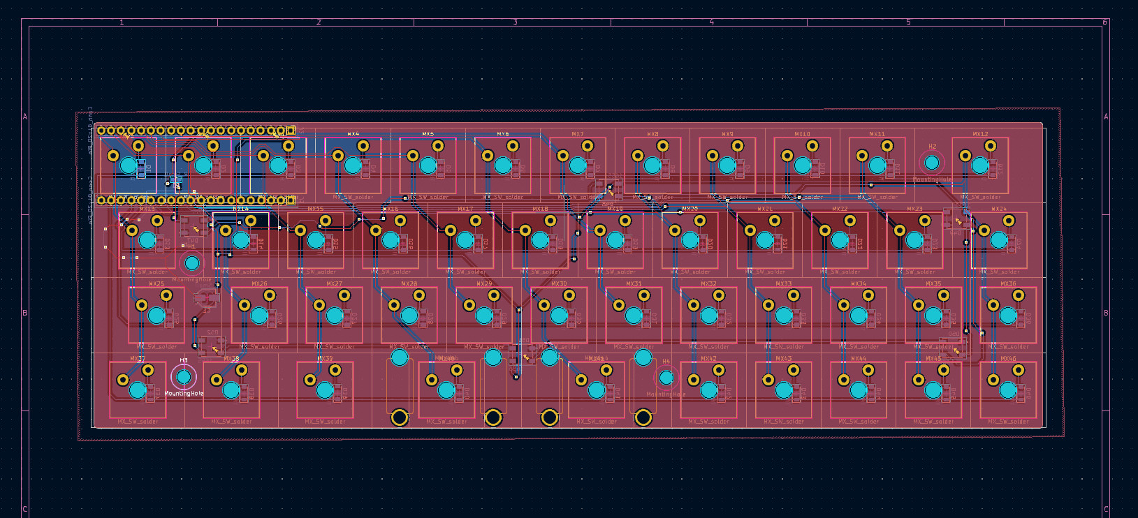
I cringe looking at how the board was wired in my last post, but hey, that's learning. Since then I've had my lovely wife @Steph go over the schematic and inform me that my conceptual knowledge of lighting an LED was indeed lacking. With help from them and the website Falstad I was able to learn that the LEDs needed to each be connected to 5v, because they're not a strip, they're individual LEDs, and they needed a capacitor placed across the power and ground lines, not in series with the power and ground lines. Being able to visualize the circuit was very helpful, and though I know it may have been wise to breadboard it I really liked the digital equivalent. Many thanks to @Steph for pulling me out of that knowledge hole, and for later teaching me about ground planes.

 Mx. Jack Nelson
Discussions
Become a Hackaday.io Member
Create an account to leave a comment. Already have an account? Log In.