If you have read my first (and way too long) log entry, you will be familiar with my first attempt at building a test jig, which looked like this:
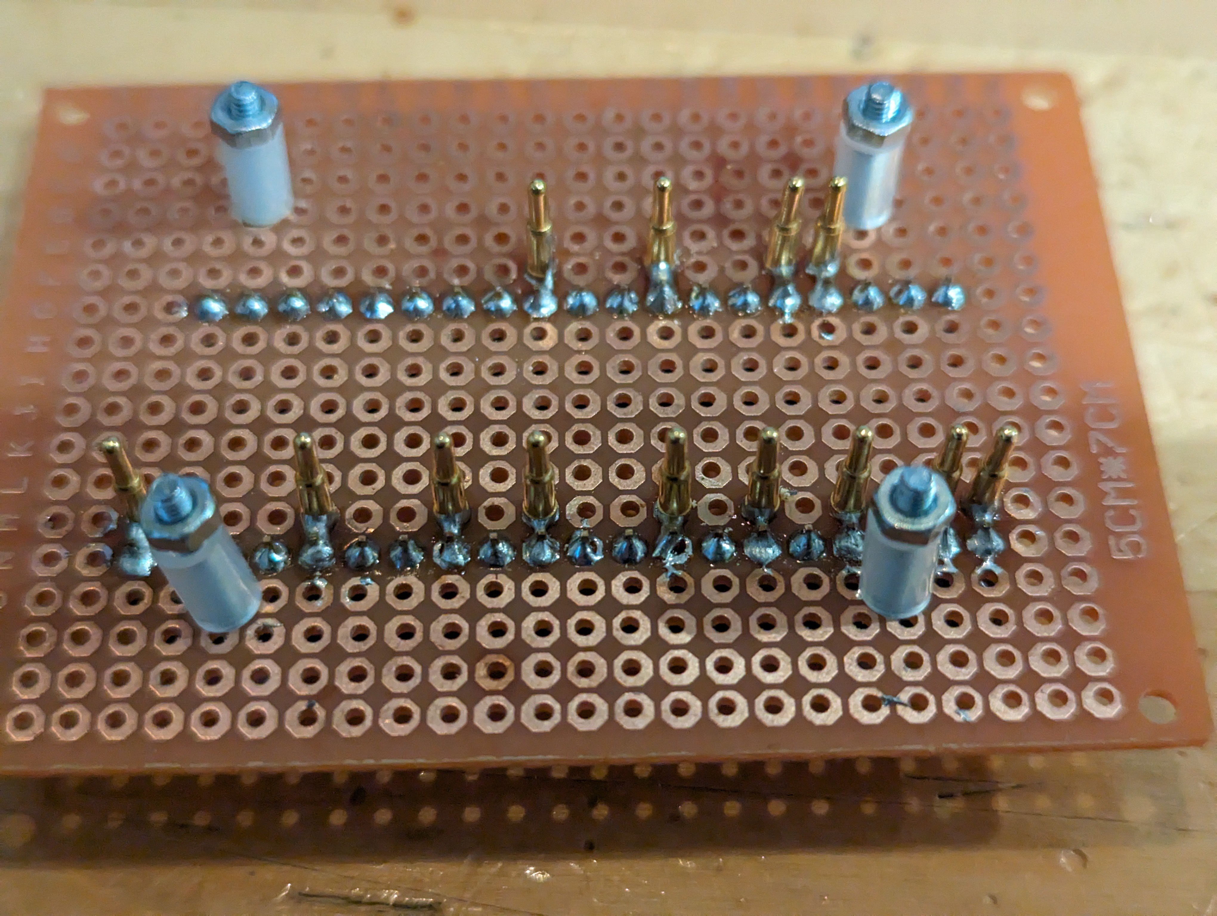
Not exactly pretty, but functional enough: slap a board to be tested on top, secure it with the bolts, and let the Pico that lives underneath do the work. I was able to test a number of boards this way without having to solder anything.
However, this is a one off, and I thought I'd build something a bit less hackish. Also, I would like to be able to test the dual-board setup, which requires to be more inventive.
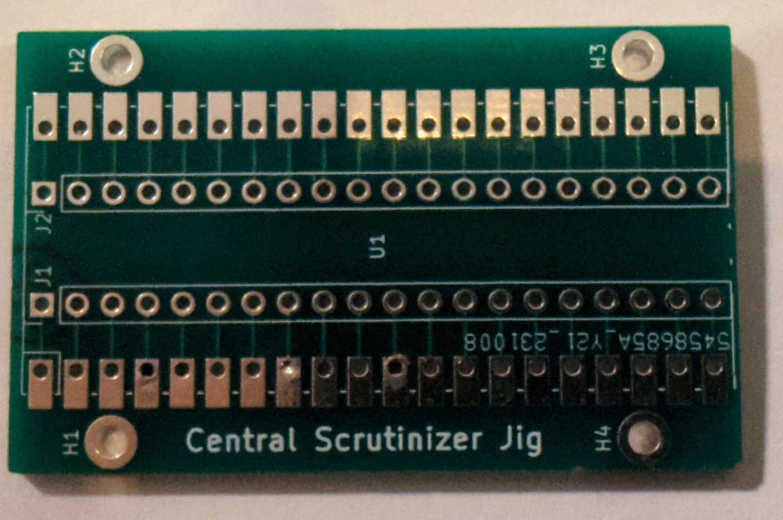
So I settled on a PCB design that would give me some flexibility: a jig PCB can either hold a board or a Pico, but not both. If you want to connect it to anything else, I have an additional connector for that in the middle:
Of course, this results in twice the number of PCBs for the same thing as my original contraption:
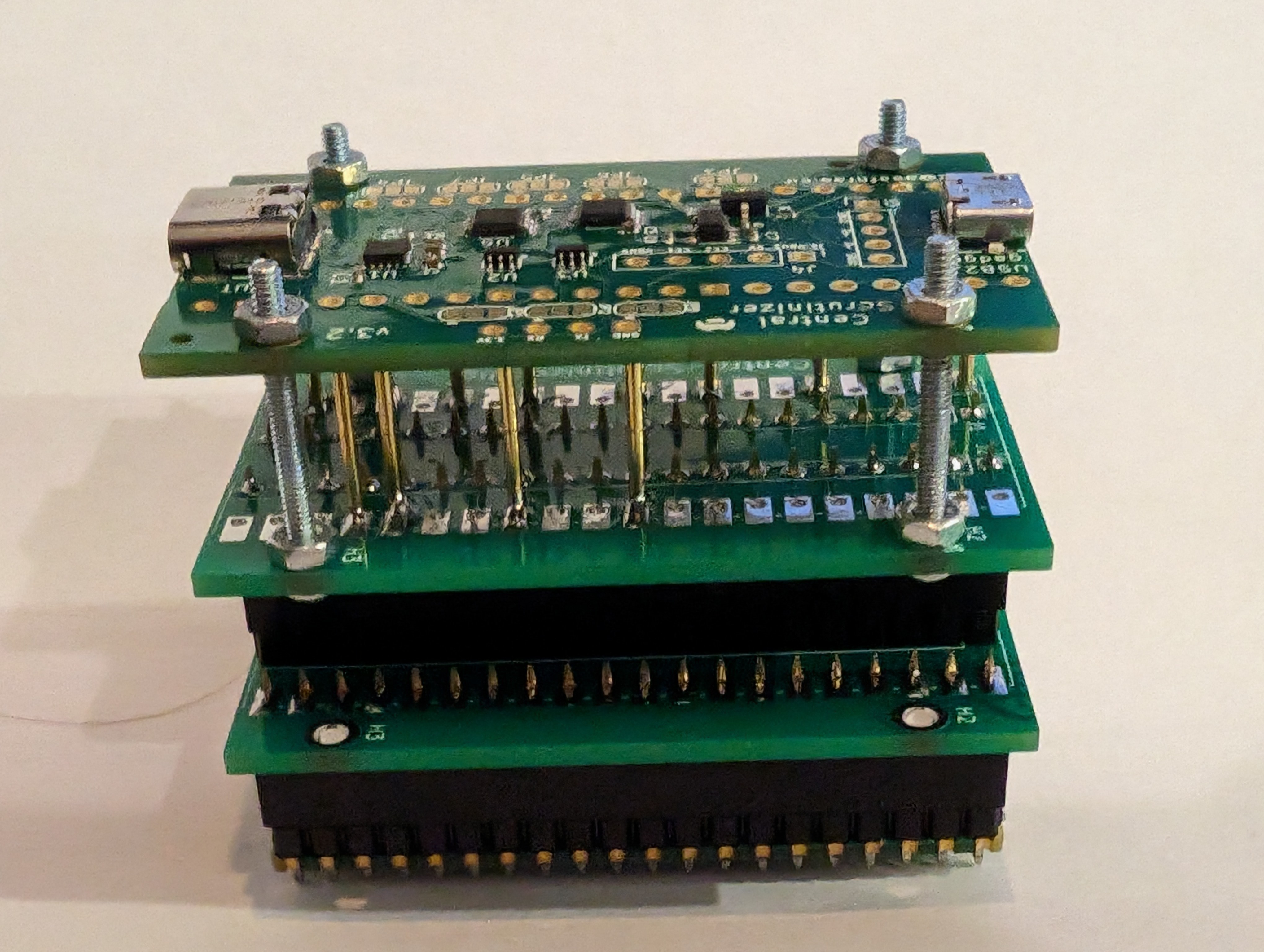
The (modest) advantage of this version is that I can swap the top interposer for one that has a different configuration. And this is not restricted to a Central Scrutinizer board either.
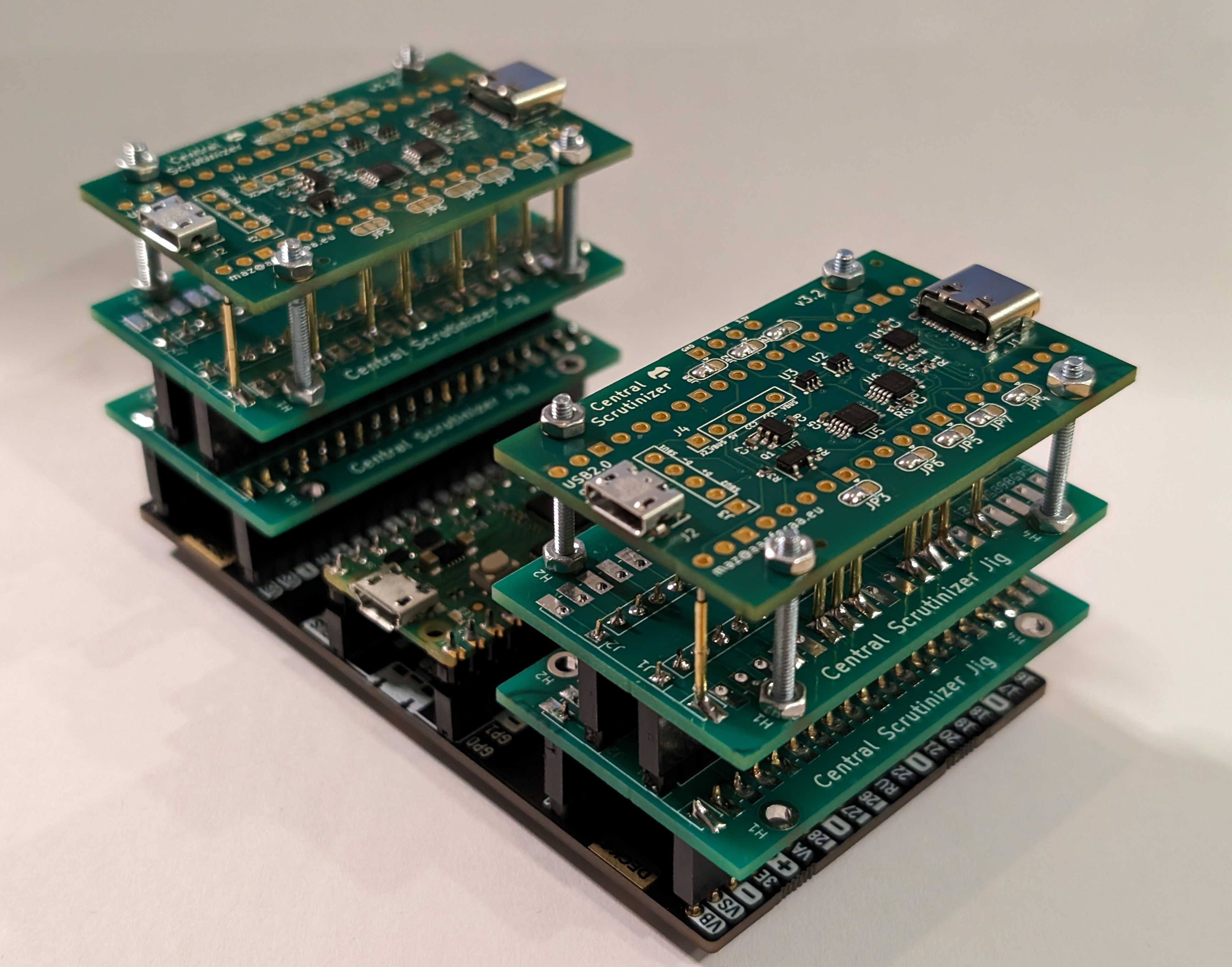
Now, back to my earlier plan of being able to test two boards at once. I found this carrier board (https://thepihut.com/products/pico-omnibus-dual-expander) that allows me to plug two boards. With two test jigs plugged in, and two CS boards to boot, that's quite a setup! I have since replaced the metal screws and bolts with nylon equivalents, which is much safer.
Of course, the PCB design is pushed out in the repo. Feel free to reuse it for something else!
Discussions
Become a Hackaday.io Member
Create an account to leave a comment. Already have an account? Log In.