 Robert
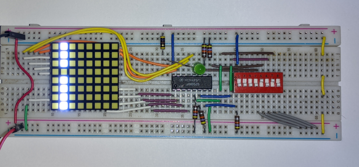
I put together a quick breadboard circuit to test the functionality of the MC14495 driver chips I purchased. I don't have a breadboard friendly common-cathode 7-segment display at the moment, so I used one column of a 8x8 matrix and a single LED to test all 9 outputs. I also added a dip switch to test the 5 inputs. Thankfully, all the chips seem to be fully functional.
The lit column is (from top to bottom) a, b, c, d, e, f, g and h+i. The currently displayed character is 'A', so all segments except d are lit. Additionally, h+i is lit because the character is a letter and j is not lit (green LED) because the data inputs are not all 1's.
Discussions
Become a Hackaday.io Member
Create an account to leave a comment. Already have an account? Log In.