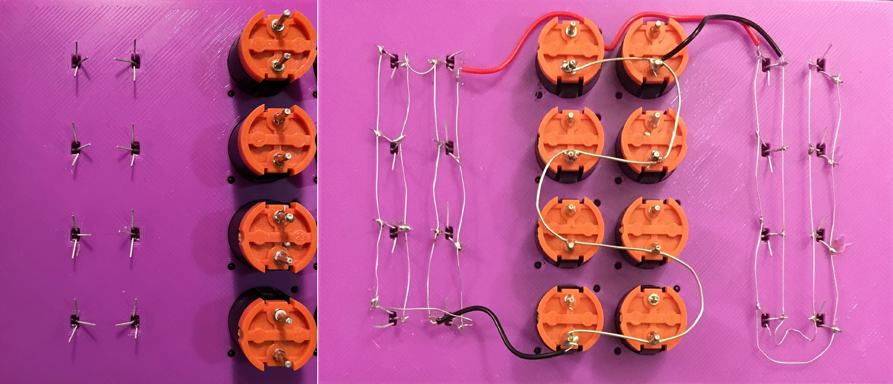
The first thing I did was to trim the leads on the SS49E sensors and spread them out a bit for easier access.

Then I wired the power connections to all the sensors and the buttons. Obviously a lot of care was taken not to introduce shorts, especially with the tiny hall effect sensors. The perfectionist in me cringes a bit looking at this, but I am determined to keep the BOM down so point-to-point wiring it is.
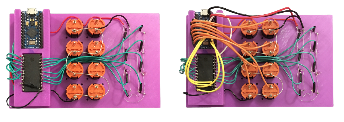
Next I wired the outputs of the 16 sensors and power to the multiplexer (left below). Finally I connected the pro Micro (right below) to the buttons, multiplexer, and project power.

Here are all the connections.
| Arduino pro Micro | CD4067BE Multiplexer | Wire Color | Other |
| VCC | +5V | Dark Orange | Also powers the sensors. |
| GND | GND | Black | Project Ground |
| A0 | Common Input (Read the channel selected by S0-S3) | White | |
| I/O Pin 2-9 | Light Orange | Button 1-8 | |
| I/O Pin 15 | S0 (These four outputs select which of the 16 analog channels to read.) | Yellow | |
| I/O Pin 14 | S1 | Yellow | |
| I/O Pin 16 | S2 | Yellow | |
| I/O Pin 10 | S3 | Yellow | |
| I0 - I15 | Green | Sensors 1-16 | |
| GND | E (This is an inverted chip select pin.) | Black |
I wrote a quick and dirty test program and discovered a couple of bad solder joints, but everything seems to be working as expected now. Software time.
 Michael Gardi
Discussions
Become a Hackaday.io Member
Create an account to leave a comment. Already have an account? Log In.