My first thought was to use an MPU6050 with an ESP32 for this project, as I had those about. The ESP32 had been used in a previous project to get an LCD display working (which turned out to be surprisingly difficult), so I decided to throw that in the mix as well; since that had used the u8g2 library, I decided to stay with Arduino-flavoured C++ for that...though really, MicroPython is much more my speed.
For a test setup, I decided to use an Ikea shelf section. It's not ideal; it's made of narrow lengths of (I think) pine glued together, which would likely complicate any measurements I took. But it had the firm advantage that I had it about and could press it into service. :-)
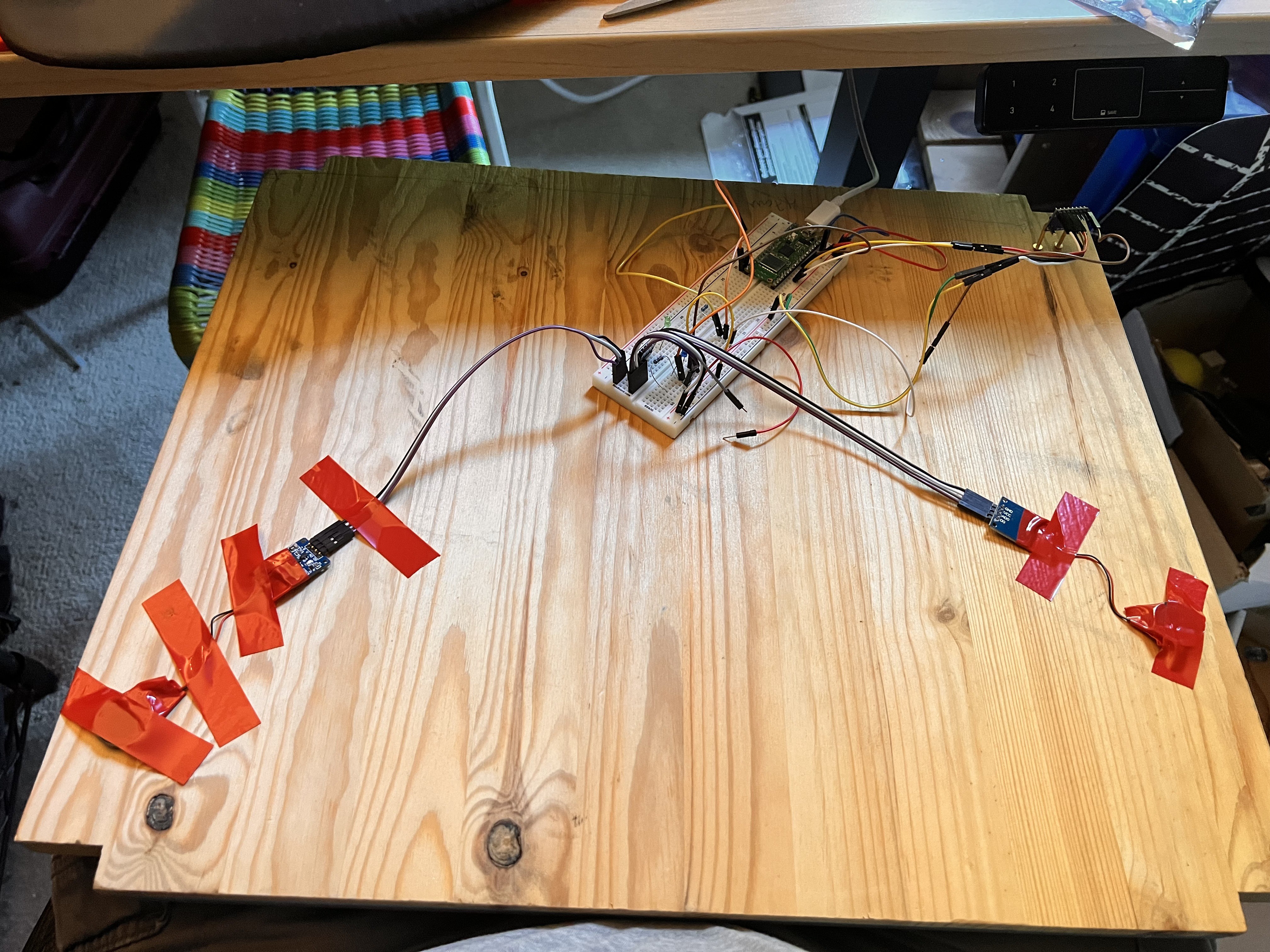
This picture shows what the setup was like:

This was taken a little longer into the process, so there are two piezo sensors (which didn't come 'til later), the breadboard has a Pi Pico (which I switched to later), and it's missing the hammer setup. But since I didn't take any other pictures at the time, this'll have to do.
Here's how it worked:
- The MPU6050 is in the top right corner. It's sitting on two right-angled picture hooks that are screwed into the board. The sensor board has two mounting holes in the corners; I put the hooks through, then rotated them outward so that they held the sensor rigidly. This did a good job of ensuring the sensor picked up vibrations from the board.
- Not shown: I had a piece of aluminum foil on the edge of the board, diagonally opposite the MPU6050. An alligator clip connected the foil to one of the GPIO pins on the ESP32. This was where I hammered the board to create the shock wave that would travel to the MPU6050.
- I used a hammer to hit the board where I had the aluminum foil. An alligator clip to the metal part of the hammer went to the +3V power supply from the ESP32.
- When the hammer hit the foil (and thus the board), the ESP32 saw the signal on that GPIO pin and noted the time.
- The MPU6050 was configured to send an interrupt when it detected vibration. When the ESP32 saw that interrupt, it noted the time.
- The difference between the two times was shown on the LCD screen (again, not in the picture ☹️).
Fairly straightforward; how did it work? As a proof of concept, pretty well: the display was nice, the principal was sound, and I was able to get it up and working without much trouble. I wasn't able to easily figure out how to reset the MPU6050 after it sent an interrupt, so I resorted to just resetting the ESP32 -- not elegant, but it worked.
But as a way to actually measure things, it was inconsistent. Given the heterogeneity of the wooden shelf, I wasn't surprised. I also became concerned about the timing resolution I could get. I tracked down the manual for one of the commercial products I'd looked at, and it said the travel time of sound in wood was around 10 microseconds/cm. That implied needing something like a 100 MHz clock speed just to be able to detect a 1 cm difference.
The ESP32 I had ran at (I think) something like 40 MHz clock speed; it turns out this is the default when programming it with the Arduino IDE. I could switch to the ESP32 toolset, which would let me bump up the clock speed to 100 MHz. I gave that a try, but compiling my application ran into problems. I went down a number of rabbit holes trying to get this sorted out -- my background is in system administration and software development, so figuring out these kinds of problems (at least at a high level) is something I'm familiar with -- but it seemed like a series of dead ends: waiting on new library versions, bugs that hadn't been addressed in quite some time, and so on.
In the end, I put this approach aside. The ESP32 code is still in the project repository (warning: it's ugly), but hasn't been touched. I found another approach -- new sensor, new language, new microcontroller -- that promised to work better. Details on that next time!
 Hugh Brown (Saint Aardvark the Carpeted)
Discussions
Become a Hackaday.io Member
Create an account to leave a comment. Already have an account? Log In.