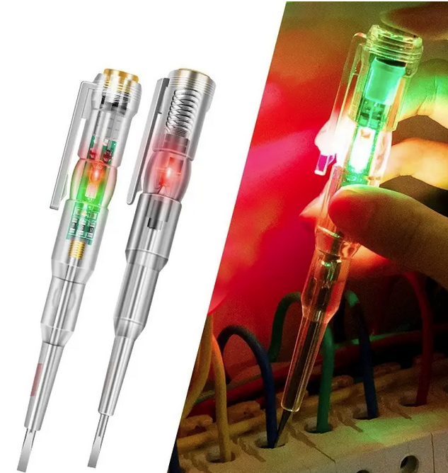
 Here is a product that probably should not be sold, not even at <2 USD. As advertised, it looks like a replacement for a voltage tester or "neon screwdriver".
  Supposedly it lights up in green if you detect ground and red of you detect the nongrounded lead of AC mains. The entire thing is extremely sensitive and the green LED even lit up when coming close to the packaged product. It seems to be a very sensitive connectivity tester, e.g. it will light up when touching both ends of the screwdriger or any grounded electrical device. The RED LED - on the other hand - did not light up under any circumstances. Highly doubtful functionality.
 The image above seems to show an older revision of the product, mine was using SMD LEDs.
Photo of product
(sorry for white balance, don't think its worth the effort to fix ut)

Included PCB with battery holder.
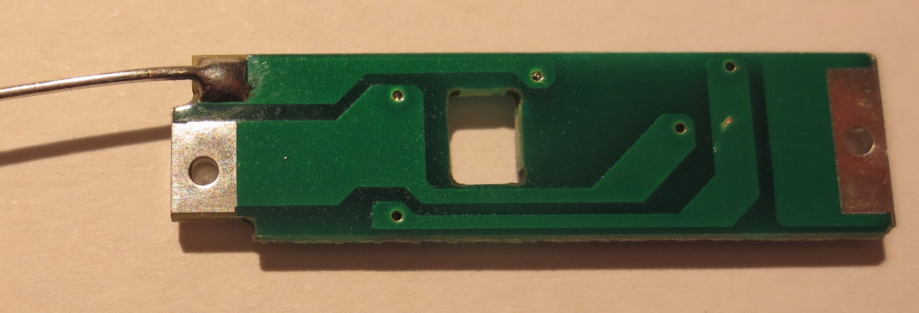
Extremely obscure and low cost construction. Both the contact to the drivers head and the battery is made by metallized PCB edges. The other pole of the battery is connect by the spring and the metal wire that sticks out. The spring also provides contact to the metallized top of the screw driver that you are support the touch.
Considering that this is a product which is used to contact live circuits under mains voltage. How many things can go wrong when assembling this? Crazy.

PCB top and bottom
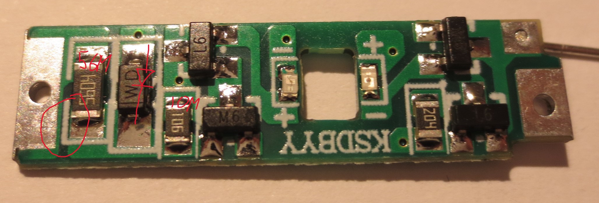
Details of the PCB are shown below. There seem to be two NPN and two PNP transistors, according to the marking. In addition to LEDs, a few resistors and a diode. The "hot" input is protected my a 5.6 Mohm resistor. There After this resistor there seems to be one path through a diode and one path that through a 10 Mohm resistor. Possibly the circuit distinguishes AC voltage and DC conduction with the idea of detecting the hot and ground wire.
The high and low voltage parts of the circuit are only separated by minimum trace spacing on the PCB. This does not really look like a safe design to me.


Potential safety hazard and lack of proper functionality. Off into the trash it goes - strong recommendation not to buy.
 Tim
Tim
Discussions
Become a Hackaday.io Member
Create an account to leave a comment. Already have an account? Log In.