 Ted Yapo
I decided to test the idea with a ring oscillator. After seeing that five inverters would oscillate in a SPICE simulation, I heated up the soldering iron and made this:
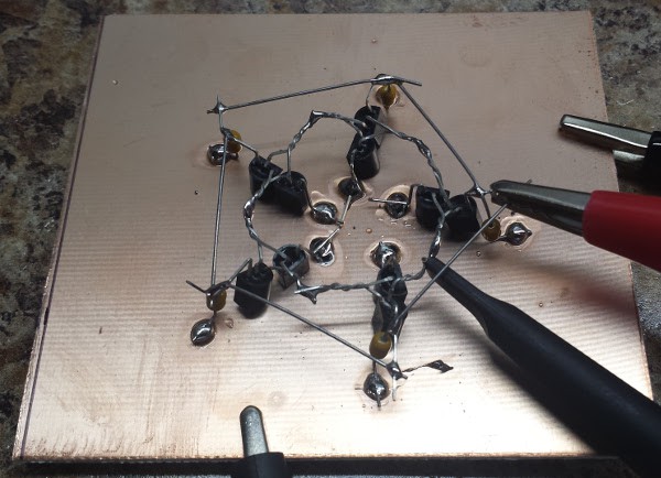
there are five inverters based on the original circuit:
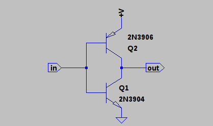
each one has a 0.47uf supply bypass capacitor. The circuit starts to oscillate at about 0.4V, but is wildly unstable. At 0.8V, it draws 30mA with stable oscillation:
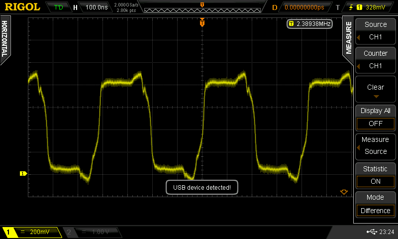
The oscillation frequency is 2.4 MHz, equal to a period of 420 ns. This implies a propagation delay of 42ns per inverter.
There are a lot of issues that would have to be solved before this becomes a usable logic family, but it's a start.
If we can figure out how to make either an AND or OR gate, we'll at least be logic-complete, then it's a matter of details.
Discussions
Become a Hackaday.io Member
Create an account to leave a comment. Already have an account? Log In.
Nice layout
Are you sure? yes | no
Oh, this needs a base resistor, of course! That will reduce the supply current at higher voltages. I saw the "antique" schematic you posted - base resistor with speedup capacitor. Makes sense.
Are you sure? yes | no
heh, "speedup capacitor" I guess that's exactly what I was talking about... saw it in-circuit, and didn't quite grasp its purpose.
Are you sure? yes | no
30mA/5= 6mA per inverter at room temperature. Not the best but could still be worse, and it's hightly dependent on a very stable power supply voltage.
Are you sure? yes | no
I think the voltage supply should vary with the ambient temperature to keep everything stable. Just add enough forced air to keep at the transistors at the same temperature and use a 2N3904 BE junction as a temperature sensor to regulate the power supply.
Are you sure? yes | no
yup.
In comparison, TTL is extremely reliable ;-)
Are you sure? yes | no
Or run a constant current source. BJTs are current mode devices.
Are you sure? yes | no
@K.C. Lee : we're entering the ECL domain here :-D
Part of the allure of this circuit is the similarity with CMOS... it stands to reason that we wish to keep this aspect :-)
Are you sure? yes | no
But, my assumption is that this works like CMOS - draws very little current when idle, this 6mA/inverter is running near full speed.
Are you sure? yes | no
no because BJT are current-driven and require current to keep conducting.
The Baker circuit with RC in parallel on the base addresses this concern, though the supply voltages need adaptations.
Are you sure? yes | no
yes, I need software that makes me think before typing.
Are you sure? yes | no
Interesting point about BJTs' being current-driven... As I understand, speed-wise they certainly switch faster when driven with a larger current... but there's no need for that level of current once they've switched. I wonder if an RC circuit could allow for fast switching, then lower drive-current to "maintain" a value. Might change the topology a bit (a lot)
Are you sure? yes | no
For OR and AND, it's simply like in CMOS : high-side has inverse topology as low-side,
AND: low-side is parallel, high side series
OR : low-side series, high side parallel
Are you sure? yes | no
I think the Vbe drop is a problem here. I can't see how to do it :-(
Are you sure? yes | no
experiment.
Are you sure? yes | no